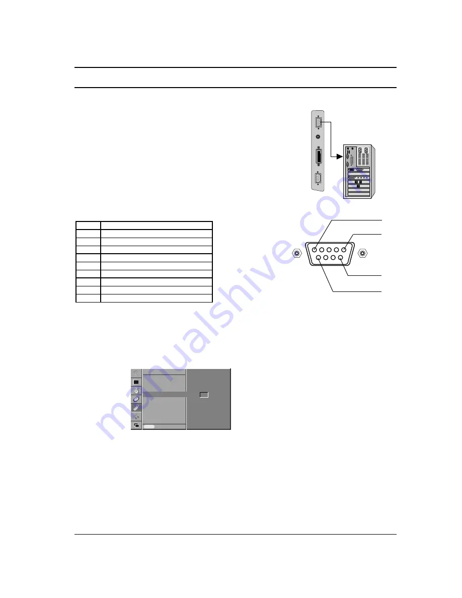
Connect the RS-232C input jack to an external control device (such
as a computer or an A/V control system) and control the set’s func-
tions externally.
RS-232C input socket
1. Connect the serial port of the control device to the RS-232C
jack on the set.
2. RS-232C connection cables are not supplied with the set.
3. The set’s remote control handset and front panel controls
(except main power) will not be functional if the set is controlled
by a PC computer or other external device.
D-Sub 9-pin male
Set ID
Use this function to specify a monitor ID number.
Refer to ‘Real Data Mapping 1’. See page 41.
1. Press the MENU button and then use the
D
/
E
button to select
the SPECIAL menu.
2. Press the
G
button and then use
D
/
E
button to select
Set ID
.
3. Press the
G
button and then use
F
/
G
button to adjust
Set ID
to choose the desired monitor ID number.
Note : The adjustment range of
Set ID
is 1 ~ 99.
Communication Parameters
• Baud rate : 115200 bps (UART)
• Data length : 8 bits
• Parity : None
• Stop bit : 1 bit
• Communication code : ASCII code
*
Use a crossed (reverse) cable.
External Control Device Setup
37
1
5
6
9
No. Pin
name
1 No
connection
2
RXD (Receive data)
3
TXD (Transmit data)
4
DTR (DTE side ready)
5
GND
6
DSR (DCE side ready)
7
RTS (Ready to send)
8
CTS (Clear to send)
9
No Connection
Language
Child Lock
Orbiter
Set ID
Prev.
SPECIAL
MENU
Set ID
G
G
1
Содержание BZ03
Страница 44: ......


