background image

11

EX

TE

R

N

AL

 E

q

U

IP

M

EN

T S

ET

U

P

CONNECTiNg WiTh A COmPONENT CABlE


To avoid damaging any equipment, never plug in any power cord until you have finished connecting 

all equipment.

■ 

Image shown may differ slightly from your device.

1

2

DC IN 12V

OPTICAL DIGITAL

AUDIO OUT

SERVICE ONLY

3

RGB IN(PC)

AUDIO IN

RS-232C IN

RGB/DVI

 SERVICE ONLY

A

B

COMPONENT / AV IN 1
COMPONENT / AV IN 2

A

R

L(MONO)

AUDIO

VIDEO

B

R

L(MONO)

AUDIO

VIDEO

L R

L R

  / DVI IN

A

R

L(MONO)

AUDIO

VIDEO

B

1

2

SERVICE ONLY

3

RGB IN (PC)

AUDIO IN RS-232C IN

RGB/DVI

SERVICE ONLY

IR BLASTER

A

B

COMPONENT / AV IN 1
COMPONENT / AV IN 2

R

L(MONO)

AUDIO

VIDEO

OPTICAL DIGITAL

AUDIO OUT

DC IN 12V

L R

L R

  / DVI IN

IR BLASTER

1

2

DC IN 12V

OPTICAL DIGITAL

AUDIO OUT

SERVICE ONLY

3

RGB IN(PC)

AUDIO IN

RGB/DVI

 SERVICE ONLY

  / DVI IN

IR BLASTER

A

R

L(MONO)

AUDIO

VIDEO

B

A

B

COMPONENT

 / AV IN 1

COMPONENT 

/ AV IN 2

L R

L R

DC IN 12V

OPTICAL DIGITAL

AUDIO OUT

SERVICE ONLY

RGB IN(PC)

AUDIO IN

RGB/DVI

 SERVICE ONLY

A

B

COMPONENT / AV IN 1
COMPONENT / AV IN 2

A

R

L(MONO)

AUDIO

VIDEO

B

R

L(MONO)

AUDIO

VIDEO

L R

L R

IR BLASTER

1

2

3

  / DVI IN

DC IN 12V

OPTICAL DIGITAL

AUDIO OUT

SERVICE ONLY

RGB IN(PC)

AUDIO IN

RGB/DVI

 SERVICE ONLY

A

B

COMPONENT / AV IN 1
COMPONENT / AV IN 2

A

R

L(MONO)

AUDIO

VIDEO

B

R

L(MONO)

AUDIO

VIDEO

L R

L R

IR BLASTER

1

2

3

  / DVI IN


1

2

DC IN 12V

OPTICAL DIGITAL

AUDIO OUT

SERVICE ONLY

3

RGB IN(PC)

AUDIO IN

RGB/DVI

 SERVICE ONLY

A

B

COMPONENT / AV IN 1
COMPONENT / AV IN 2

A

R

L(MONO)

AUDIO

VIDEO

B

R

L(MONO)

AUDIO

VIDEO

L R

L R

  / DVI IN

IR BLASTER

R

L(MONO)

AUDIO

VIDEO

1

2

DC IN 12V

OPTICAL DIGITAL

AUDIO OUT

SERVICE ONLY

3

RGB IN(PC)

AUDIO IN

RGB/DVI

 SERVICE ONLY

  / DVI IN

IR BLASTER

A

R

L(MONO)

AUDIO

VIDEO

B

A

B

COMPONENT /

 AV IN 1

COMPONENT /

 AV IN 2

R

L(MONO)

AUDIO

VIDEO

L R

L R

1

2

DC IN 12V

OPTICAL DIGITAL

AUDIO OUT

SERVICE ONLY

3

AUDIO IN

RGB/DVI

 SERVICE ONLY

A

B

COMPONENT / AV IN 1
COMPONENT / AV IN 2

A

R

L(MONO)

AUDIO

VIDEO

B

R

L(MONO)

AUDIO

VIDEO

L R

L R

  / DVI IN

IR BLASTER

RGB IN (PC)

1

2

DC IN 12V

OPTICAL DIGITAL

AUDIO OUT

SERVICE ONLY

3

RGB IN(PC)

AUDIO IN

RGB/DVI

 SERVICE ONLY

A

B

COMPONENT / AV IN 1
COMPONENT / AV IN 2

A

R

L(MONO)

AUDIO

VIDEO

B

R

L(MONO)

AUDIO

VIDEO

L R

L R

  / DVI IN

IR BLASTER

1

2

Component input ports

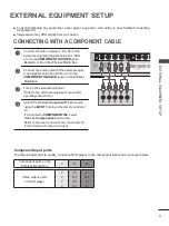
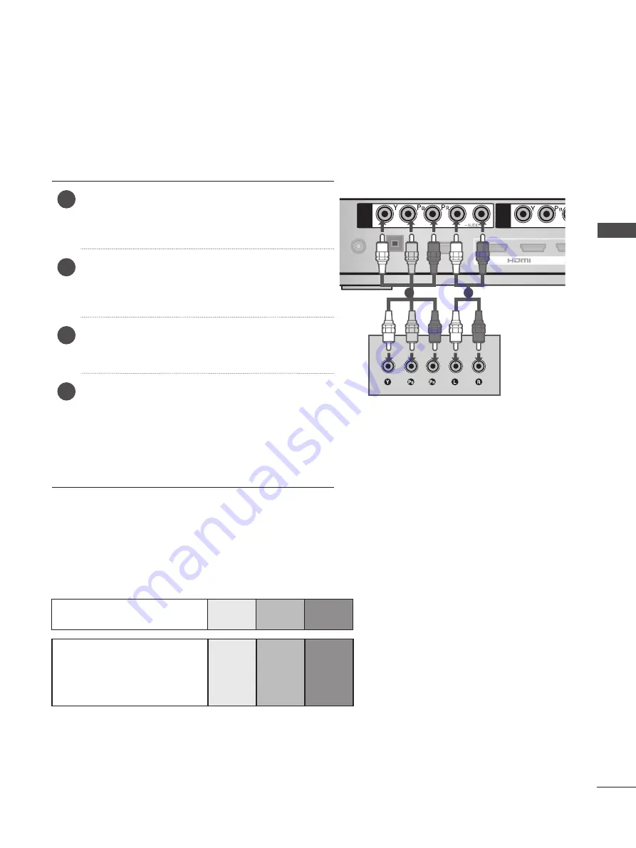
To achieve better picture quality, connect a DVD player to the component input ports as shown below.

 Component ports on the 

Wireless Media Box

Y

P

B

P

R

Video output ports 

on DVD player

Y

P

B

P

R

Y

B-Y

R-Y

Y

Cb

Cr

Y

Pb

Pr

1

Connect the video outputs (Y, P

B

, P

R

) of the 

external equipment (digital set-top box, DVD, 

etc.) to the 

COmPONENT iN VidEO

 jacks 

labeled A or B on the Wireless Media Box. 

2

Connect the audio output of the external equip-

ment (digital set-top box, DVD, etc.) to the 

COmPONENT iN AUdiO

 jacks on the Wireless 

Media Box.

3

Turn on the external equipment. 
(Refer to the external equipment's manual for 

operating instructions.)

4

Select the Wireless 

Component1 

input source 

using the 

iNPUT

 button on the remote control of 

TV. 
If connected to 

COmPONENT iN2

, select 

Wireless 

Component2

 input source. 

Refer to the user manual of the connected TV 

for the format of component input.


ExTErNAl EqUiPmENT SETUP

Содержание AN-WL100W

Страница 1: ...www lg com OWNER S MANUAL WIRELESS MEDIA BOX Please read this manual carefully before operating your set and retain it for future reference ...

Страница 2: ...rference 9 Attaching the IR blaster 10 Optimal location of external device with IR Blaster installed 10 external equipment setup Connecting with a Component cable 11 Connecting with an HDMI cable 12 Connecting with an HDMI to DVI cable 13 Connecting with RCA cable 14 Digital Audio Out Setup 15 Connecting with RGB 15 Supported Display Resolution 16 Watching TV Program control Turning on the Wireles...

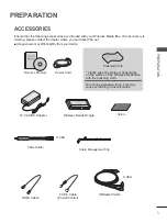
Страница 3: ...from your device Owner s Manual Power Cord 12 V AC DC Adapter 20 Pin Cable Power Control HDMI Cable IR Blaster Cable X 2EA Wireless Ready Dongle Velcro Cable Holder X 2EA Cable Management Clip Polishing Cloth Lightly wipe any stains or fingerprints on the surface of the Wireless Media Box with the polishing cloth Do not use excessive force This may cause scratching or discolouration Preparation Ac...

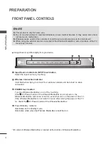
Страница 4: ... touching If the I Power button of the Wireless Media Box is not turned on the Wireless Media Box will not be turned on even when turn on the power of the TV If the Wireless Media Box is not turned on even after turning the power of the TV on check the I Power button of the Wireless Media Box Power Standby Indicator Illuminates red in standby mode Illuminates white when the Wireless Media Box is s...

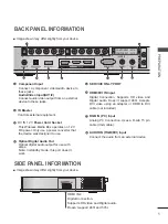
Страница 5: ... Analog PC Connection Uses a D sub 15 pin cable VGA cable AUDIO IN RGB DVI Input Connect the audio from an external device 1 2 3 7 8 5 6 Image shown may differ slightly from your device 4 IN 4 A R L MONO AUDIO VIDEO B 1 2 SERVICE ONLY 3 RGB IN PC AUDIO IN RGB DVI SERVICEONLY IR BLASTER A B COMPONENT AV IN 1 COMPONENT AV IN 2 R L MONO AUDIO VIDEO OPTICALDIGITAL AUDIO OUT DC IN 12V L R L R DVI IN 1 ...

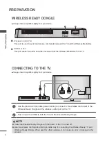
Страница 6: ...Dongle 1 Use the provided 20 pin cable power control to connect to the wireless control port of the Wireless Ready Dongle and the wireless control port on the TV 2 Now connect the HDMI to both the TV and the Wireless Ready Dongle 1 2 Image shown may differ slightly from your device NOTE Install the Wireless Ready Dongle with the power of the TV turned off Use the wireless control jack and 20 pin c...

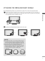
Страница 7: ...ocation engraved on the TV 1 Now place the Wireless Ready Dongle onto the Velcro pad 2 or Velcro or NOTE The attaching location on the Wireless Ready Dongle can differ by model Check the engraving on the back cover and attach the cable according to the engraving Clean the part where the magic tape Velcro is attached using the supplied brush and attach the part by pressing the area evenly for 1 min...

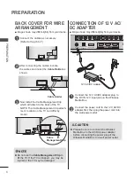
Страница 8: ...be damaged Connect the cables as necessary Refer to the p 6 to 7 1 After connecting the cables bundle the cables and install the Cable Holder as shown 2 Cable Holder Cable Management Clip 1 1 2 Connect the 12 V AC DC adapter plug to the DC IN 12V input jack on the Wireless Media Box Connect the power cord to the 12 V AC DC adapter first then plug the power cord into the wall power outlet CAUTION P...

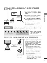
Страница 9: ...ese problems occur take the following actions Maintain a distance of at least 5 m 16 feet between the TV and another device with a 5 GHz band Position the Media Box in a location clos er to the TV Place the Media Box in a higher position a minimum of 1 m is recommended Please set your wireless LAN to 2 4 GHz Band channel 1 to 11 Please refer the manual of your router for detail information If it i...

Страница 10: ... efficiently IR Receiver 1 2 DC IN 12V OPTICAL DIGITAL AUDIO OUT SERVICE ONLY 3 RGB IN PC AUDIO IN RGB DVI SERVICEONLY A B COMPONENT AV IN 1 COMPONENT AV IN 2 A R L MONO AUDIO VIDEO B R L MONO AUDIO VIDEO IR BLASTER L R L R DVI IN Install the external device with the IR Blaster installed at a location it is not affected by the sig nal from the remote controller to the TV When the external device w...

Страница 11: ... Component ports on the Wireless Media Box Y PB PR Video output ports on DVD player Y PB PR Y B Y R Y Y Cb Cr Y Pb Pr 1 Connect the video outputs Y PB PR of the external equipment digital set top box DVD etc to the COMPONENT IN VIDEO jacks labeled A or B on the Wireless Media Box 2 Connect the audio output of the external equip ment digital set top box DVD etc to the COMPONENT IN AUDIO jacks on th...

Страница 12: ... Box 2 Turn on the external equipment 3 Select Wireless HDMI1 Wireless HDMI2 Wireless HDMI3 or Wireless HDMI4 input source using the INPUT button on the remote control of TV Refer to the user manual of the connected TV for the format of HDMI input NOTE The Wireless Media Box can receive video and audio signals simultaneously when using an HDMI cable If the DVD does not support Auto HDMI you must s...

Страница 13: ...ox or the DVI output of the PC to HDMI DVI IN 1 HDMI DVI IN 2 or HDMI DVI IN 3 jack on the Wireless Media Box 2 Connect the audio output of the digital set top box or the PC audio output to the AUDIO IN RGB DVI jack on the Wireless Media Box 3 Turn on the digital set top box or the PC and the Wireless Media Box Refer to the digital set top box or the PC manual for operating instructions 4 Select W...

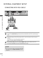
Страница 14: ...IDEO L R L R DVI IN IR BLASTER RGB IN PC Connecting with RCA cable 1 Camcorder Video Game Set or NOTE If you have a mono VCR connect the audio cable from the VCR to the AUDIO L MONO jack of the media box 1 Connect the AUDIO VIDEO jacks between Wireless Media Box and VCR or external equip ment 2 Insert a video tape into the VCR and press PLAY on the VCR Refer to the VCR owner s manual Or Operate th...

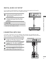
Страница 15: ... the OPTICAL DIGITAL AUDIO OUT port on the Wireless Media Box 2 Connect the other end of the optical cable to the digital audio Optical input on the audio equipment Connecting with RGB You can also connect devices using the RGB input This connection uses a standard VGA cable D Sub 15 pin cable This Wireless Media Box supports Plug and Play capability meaning that the PC adjusts automatically to th...

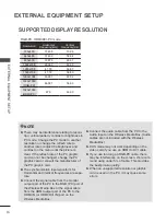
Страница 16: ...from the HDMI output port of the PC to the HDMI IN or HDMI DVI IN port on the Wireless Media Box Connect the audio cable from the PC to the Audio input on the Wireless Media Box Audio cables are not included with the Wireless Media Box DOS mode may not work depending on the video card if you use an HDMI to DVI cable If you use too long an RGB PC cable there may be interference on the screen We rec...

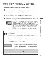
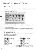
Страница 17: ... Left icon is to distinguish the external input of TV and the wireless external input of Wireless Media Box After the Wireless Ready Dongle is successfully installed wireless external input will be shown additionally in the TV menu related to external input Input List Input Label Timer Input Block and Picture Wizard Operate the external input of Wireless Media Box using the remote controller of th...

Страница 18: ...the MENU EXIT button to return to normal TV viewing Press the BACK button to move to the previous menu screen 1 Select OPTION 2ENTER Select IR Blaster 3ENTER Select On or Input list IR Blaster Setup Only input signals which are connected to a TV or Wireless Media Box can be activated and selected This is the screen when the Wireless Ready Dongle is connected to HDMI DVI IN 1 HDMI terminal connecte...

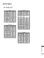
Страница 19: ...0 HITACHI NEC LG NEC MITSUBISHI JVC HITACHI M50110 GO VIDEO SAA3004 AUDIO BRAND CODE DENON LRC3715 YAMAHA NEC MARANTZ SAA3010 INTEGRA ONKYO NEC H K NEC PIONEER NEC BOSE NEC LEXICON uPD6121 ROTEL uPD6121 SHERWOOD uPD6121 XM SAA3010 REALISTIC TC9148 PARASOUND TC9132P INSIGNIA SAA3004 CBL SAT BRAND CODE S A PIONEER D6108 MOTOROLA MOTOROLA DIRECTV DIRECTV MOXI MOXI VOOM BU5962 SAMSUNG uPD6121 LG NEC P...
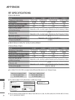
Страница 20: ...U NII II U NII II extended U NII III Frequency range GHz 5 15 to 5 25 5 25 to 5 35 5 47 to 5 725 5 725 to 5 825 Transmission OFDM OFDM OFDM OFDM RF Output Power Average dBm 13 13 13 13 Antenna Gain Peak dBi 3 36 3 05 2 72 3 17 Channel Table MHz Center frequency Depends on the country region Please see the Frequency Table Channel units 2 to 11 Depends on the country region Please see the Frequency ...

Страница 21: ...ˁˆˈʳ ˈˁˇˊʳ ʳ ʳˈˁˊ ˈʳ ˈˁˊ ˈʳ ʳ ʳˈˁˋˈ ˈˁˊ ˈʳ ʳ ʳˈˁˋˈ ˈˁˊ ˈʳ ʳ ʳˈˁˋˈ ˈˁ ˈʳ ʳ ʳˈˁ ˈʳ ˈˁ ˈʳ ʳ ʳˈˁˆˈʳ ˈˁˇˊʳ ʳ ʳˈˁˊ ˈʳ ˈˁ ˈʳ ʳ ʳˈˁ ˈʳ ˈˁ ˈʳ ʳ ʳˈˁˆˈʳ ˈˁˇˊʳ ʳ ʳˈˁˊ ˈʳ ˈˁ ˈʳ ʳ ʳˈˁˆˈʳ ˈˁˇˊʳ ʳ ʳˈˁˊ ˈʳ ˈˁ ˈʳ ʳ ʳˈˁ ˈʳ ˈˁ ˈʳ ʳ ʳˈˁˆˈʳ Argentina Brazil Hongkong Jordan Peru South Africa Thailand CANADA US Philippines Saudi Arabia Chile Egypt Malaysia Mexico India Singapore Columbia Honduras Nicaragua Venezuela Isra...

Страница 22: ...ions shown above may be changed without prior notice for quality improvement Product Specifications Troubleshooting The video function does not work No picture No sound Check whether the TV and the Wireless Media Box are turned on Is the power cord inserted correctly into the adapter Is the adapter plug inserted correctly into the Wireless Media Box No or poor color or poor picture Adjust Color in...

Страница 23: ... is turned on Refer to the p 17 Check whether an external device is connected to Wireless Media Box Only the wireless input with the external device connected will be activated It reconnects after wire less connection is estab lished This happens when there is wireless interference from surrounding devices or when the wireless signal is weak Check the installation range of the Wireless Media Box R...

Страница 24: ...EG Group copyright 1991 1998 Thomas G Lane libmng copyright 2000 2007 Gerard Juyn Glenn Randers Pehrson libpng copyright 1998 2008 Glenn Randers Pehrson ncurses copyright 1998 Free Software Foundation Inc openSSL cryptographic software written by Eric Young software written by Tim Hudson software developed by the OpenSSL Project for use in the OpenSSL Toolkit http www openssl org strace copyright ...

Страница 25: ...25 appendix Record the model number and serial number of the TV Refer to the label on the back cover and quote this information to your dealer when requiring any service Model Serial No ...

Отзывы: