3-20
Service Manual
4045-XXX
Hardware Test Mode
In addition to the Hardware Tests of the Diagnostic Mode, the
Hardware Test Mode lets you check various hardware components.
This mode is unique as it operates only when the controller board is
removed. This eliminates the controller board as the failing FRU
since the controller board is not part of the test.
To enter the Hardware Test Mode:
1. Turn the printer off.
2. Disconnect all cables connected to the controller board.
3. Remove the controller board and shield assembly from the
printer.
4. Turn the printer on.
The following menu items are displayed on the operator panel:
Op Panel Test
Main Motor
Solenoid Test
Tray 2 Motor
Mirror Motor
Sensor Monitor
Cooling Fan (status)
Fuser Ctrl
Erase Lamp
Reset Test Mode
Engine Firmware
Note:
The Operator Panel Test is the first menu item to appear on
the operator panel when the printer is powered on in the Hardware
Test Mode. You can scroll through the menu items to select the next
test. However, the printer must be powered off and on to display the
Operator Panel Test again once you scroll past it. You can scroll
forward and backward through the other tests without powering the
printer off and on.
Service Tip: If "Engine Service" appears on the operator panel once
the printer is turned on, one of the operator panel buttons is stuck.
Содержание Optra M410
Страница 6: ...vi Service Manual 4045 XXX ...
Страница 8: ...viii Service Manual 4045 XXX Class 1 Laser Statement Label ...
Страница 14: ...xiv Service Manual 4045 XXX Japanese Laser Notice Chinese Laser Notice ...
Страница 19: ...Notices and Safety Information xix 4045 XXX Chinese Safety Information Korean Safety Information ...
Страница 20: ...xx Service Manual 4045 XXX ...
Страница 26: ...1 6 Service Manual 4045 XXX ...
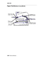
Страница 102: ...3 28 Service Manual 4045 XXX Paper Path Sensor Locations ...
Страница 103: ...Diagnostic Aids 3 29 4045 XXX Cable Locations ...
Страница 104: ...3 30 Service Manual 4045 XXX ...
Страница 116: ...4 12 Service Manual 4045 XXX 5 Remove the cooling fan ...
Страница 137: ...Connector Locations 5 3 4045 XXX ...
Страница 142: ...5 8 Service Manual 4045 XXX J17 MMF Input Sensor 1 MMF Paper Input Sensor 2 Ground 3 5 V dc Connector Pin No Signal ...
Страница 143: ...Connector Locations 5 9 4045 XXX ...
Страница 145: ...Connector Locations 5 11 4045 XXX ...
Страница 147: ...Connector Locations 5 13 4045 XXX ...
Страница 148: ...5 14 Service Manual 4045 XXX ...
Страница 150: ...6 2 Service Manual 4045 XXX Assembly 1 Covers ...
Страница 152: ...6 4 Service Manual 4045 XXX Assembly 1 Covers continued ...
Страница 154: ...6 6 Service Manual 4045 XXX Assembly 2 Frame ...
Страница 156: ...6 8 Service Manual 4045 XXX Assembly 3 Printhead ...
Страница 158: ...6 10 Service Manual 4045 XXX Assembly 4 Paper Feed Multipurpose Unit ...
Страница 160: ...6 12 Service Manual 4045 XXX Assembly 5 Paper Feed Alignment ...
Страница 162: ...6 14 Service Manual 4045 XXX Assembly 6 Paper Feed Output ...
Страница 164: ...6 16 Service Manual 4045 XXX Assembly 7 Main Drive ...
Страница 166: ...6 18 Service Manual 4045 XXX Assembly 8 Developer Drive ...
Страница 168: ...6 20 Service Manual 4045 XXX Assembly 9 Fuser ...
Страница 170: ...6 22 Service Manual 4045 XXX Assembly 9 Fuser continued ...
Страница 172: ...6 24 Service Manual 4045 XXX Assembly 10 Transfer ...
Страница 174: ...6 26 Service Manual 4045 XXX Assembly 11 Charging ...
Страница 176: ...6 28 Service Manual 4045 XXX Assembly 12 Electronics ...
Страница 178: ...6 30 Service Manual 4045 XXX Assembly 12 Electronics continued ...
Страница 180: ...6 32 Service Manual 4045 XXX Assembly 12 Electronics continued ...
Страница 182: ...6 34 Service Manual 4045 XXX Assembly 13 250 Sheet Tray ...
Страница 184: ...6 36 Service Manual 4045 XXX Assembly 14 500 Sheet Tray ...
Страница 186: ...6 38 Service Manual 4045 XXX Assembly 14 500 Sheet Tray continued ...


