


2-56
Service Manual
5016-001
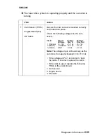
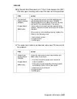
C The fuser drive system is operating properly and the cam disk is
not turning.
FRU
Action
1
Contact Cam
Solenoid
CRF Cable
Engine Board
Check the solenoid for proper operation,
making sure it picks during POR cycle.
Disconnect the solenoid and check the
resistance on the solenoid cable. It should
measure approximately 65 ohms. If incorrect,
replace the solenoid.
Check the voltages on the solenoid cable
connector.
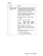
Check the following voltages on the contact
cam solenoid cable connector:
Pin #
Signal
Voltage
Voltage
Voltage
Static
Picked
1 (Red)
+24 V dc
+24 V dc
+24 V dc
2 (Black)
-SL2ON
+24 V dc
0 V - +24 V dc
Note: All voltages are approximate.
If the voltage on Pin 1 is incorrect, check
continuity of the CRF cable to the cam
solenoid.
• If incorrect, replace the cable.
• If correct, replace the engine board.
2
Motor Mounting Stay
Assembly
Check the clutch spring, clutch boss, clutch
disk and gear C4 for signs of wear, broken
teeth or binds. Repair or replace the motor
mounting stay assembly if a problem is found.
Содержание Optra C710
Страница 17: ...Notices and Safety Information xvii 5016 001 Japanese Laser Notice Chinese Laser Notice ...
Страница 18: ...xviii Service Manual 5016 001 Korean Laser Notice ...
Страница 23: ...Notices and Safety Information xxiii 5016 001 Korean ...
Страница 24: ...xxiv Service Manual 5016 001 ...
Страница 44: ...1 20 Service Manual 5016 001 ...
Страница 198: ...2 132 Service Manual 5016 001 ...
Страница 222: ...3 24 Service Manual 5016 001 ...
Страница 232: ...4 10 Service Manual 5016 001 LVPS Assembly Removal ...
Страница 250: ...4 28 Service Manual 5016 001 ...
Страница 251: ...Connector Locations 5 1 5016 001 5 Connector Locations Engine Board ...
Страница 255: ...Connector Locations 5 5 5016 001 Belt Position Sensor Board Belt Position Sensor Board Connector CN200 Engine board ...
Страница 256: ...5 6 Service Manual 5016 001 Connector Locations for Options 2nd Paper Option 250 250 Paper Option ...
Страница 260: ...5 10 Service Manual 5016 001 Electrical Components Sensor Switch Locations ...
Страница 263: ...Connector Locations 5 13 5016 001 Printer Circuit Board Locations Fan Motor Locations ...
Страница 264: ...5 14 Service Manual 5016 001 Solenoid Clutch Locations ...
Страница 268: ...5 18 Service Manual 5016 001 ...
Страница 270: ...6 2 Service Manual 5016 001 ...
Страница 272: ...7 2 Service Manual 5016 001 Assembly 1 Fuser ...
Страница 274: ...7 4 Service Manual 5016 001 Assembly 2 Fuser ...
Страница 276: ...7 6 Service Manual 5016 001 Assembly 2 Cont Fuser ...
Страница 278: ...7 8 Service Manual 5016 001 Assembly 3 Transfer ...
Страница 280: ...7 10 Service Manual 5016 001 Assembly 4 Frames ...
Страница 282: ...7 12 Service Manual 5016 001 Assembly 5 Frames Left Side ...
Страница 284: ...7 14 Service Manual 5016 001 Assembly 5 Cont Frames Left Side ...
Страница 286: ...7 16 Service Manual 5016 001 Assembly 6 Frames Right Side ...
Страница 288: ...7 18 Service Manual 5016 001 Assembly 6 Cont Frames Right Side ...
Страница 290: ...7 20 Service Manual 5016 001 Assembly 7 Frames Right Side 2 ...
Страница 292: ...7 22 Service Manual 5016 001 Assembly 7 Cont Frames Right Side 2 ...
Страница 294: ...7 24 Service Manual 5016 001 Assembly 8 Frames Right Side 3 ...
Страница 296: ...7 26 Service Manual 5016 001 Assembly 9 Carriage Block ...
Страница 298: ...7 28 Service Manual 5016 001 Assembly 10 Base Frame ...
Страница 300: ...7 30 Service Manual 5016 001 Assembly 11 Front Cover Assembly ...
Страница 302: ...7 32 Service Manual 5016 001 Assembly 11 Cont Front Cover Assembly ...
Страница 303: ...Parts Catalog 7 33 5016 001 Assembly 11 Asm Index Part Number Units Description 11 34 12G1157 1 Strap Front Cover ...
Страница 304: ...7 34 Service Manual 5016 001 Assembly 12 Front Cover Assembly 2 ...
Страница 306: ...7 36 Service Manual 5016 001 Assembly 12 Cont Front Cover Assembly 2 ...
Страница 308: ...7 38 Service Manual 5016 001 Assembly 13 Feed Unit ...
Страница 310: ...7 40 Service Manual 5016 001 Assembly 14 Laser Scanner Unit ...
Страница 312: ...7 42 Service Manual 5016 001 Assembly 14 Cont Laser Scanner Unit ...
Страница 314: ...7 44 Service Manual 5016 001 Assembly 15 Cassette ...
Страница 316: ...7 46 Service Manual 5016 001 Assembly 16 Upper Covers ...
Страница 318: ...7 48 Service Manual 5016 001 Assembly 16 Cont Upper Covers ...
Страница 320: ...7 50 Service Manual 5016 001 Assembly 17 Covers ...
Страница 322: ...7 52 Service Manual 5016 001 Assembly 18 Covers Frame 250 Tray Option ...
Страница 324: ...7 54 Service Manual 5016 001 Assembly 18 Cont Covers Frame 250 Option ...
Страница 326: ...7 56 Service Manual 5016 001 Assembly 19 Middle Roll Unit 250 Tray Option ...
Страница 328: ...7 58 Service Manual 5016 001 Assembly 20 250 250 Tray Option Lower Unit ...
Страница 330: ...7 60 Service Manual 5016 001 Assembly 21 Duplex Unit Option 2 ...
Страница 332: ...7 62 Service Manual 5016 001 Assembly 21 Cont Duplex Unit Option 2 ...
Страница 334: ...7 64 Service Manual 5016 001 Assembly 22 Cassette Upper Section ...
Страница 336: ...7 66 Service Manual 5016 001 Assembly 23 Cassette Rear Section 1 ...
Страница 338: ...7 68 Service Manual 5016 001 Assembly 24 Cassette Rear Section 2 ...
Страница 340: ...7 70 Service Manual 5016 001 Assembly 25 Duplex Option Lower Section 1 ...
Страница 342: ...7 72 Service Manual 5016 001 Assembly 25 Cont Duplex Lower Section 1 ...
Страница 344: ...7 74 Service Manual 5016 001 Assembly 26 Duplex Option Lower Section 2 ...
Страница 346: ...7 76 Service Manual 5016 001 Assembly 27 Duplex Option Lower Section 3 ...
Страница 348: ...7 78 Service Manual 5016 001 Assembly 28 Cassette Lower Section 4 ...
Страница 350: ...7 80 Service Manual 5016 001 Assembly 29 Duplex Option Lower Section 5 ...
Страница 352: ...7 82 Service Manual 5016 001 Assembly 29 Cont Duplex Option Lower 5 ...
Страница 367: ......
Страница 368: ......
Страница 369: ......


