


Diagnostic information
2-99
5060-00
x
943 Error code
Black toner metering cycle (TMC)
Toner metering cycle (TMC) is where the code and electronics in the printer sense an addition of toner in the
cartridge developing area. If the printer is expecting a toner addition cycle but one is not detected, a 94x TMC
Error is displayed.
Replacement of the cartridge may fix the problem temporarily if the problem is with the printer. Only replace the
cartridge if there are no problems with the printer or if the cartridge is known to be defective.
Note:
Before proceeding with this service check, observe the error log for repetitive occurrences of a 94
x
service error.
Step
Actions and questions
Yes
No
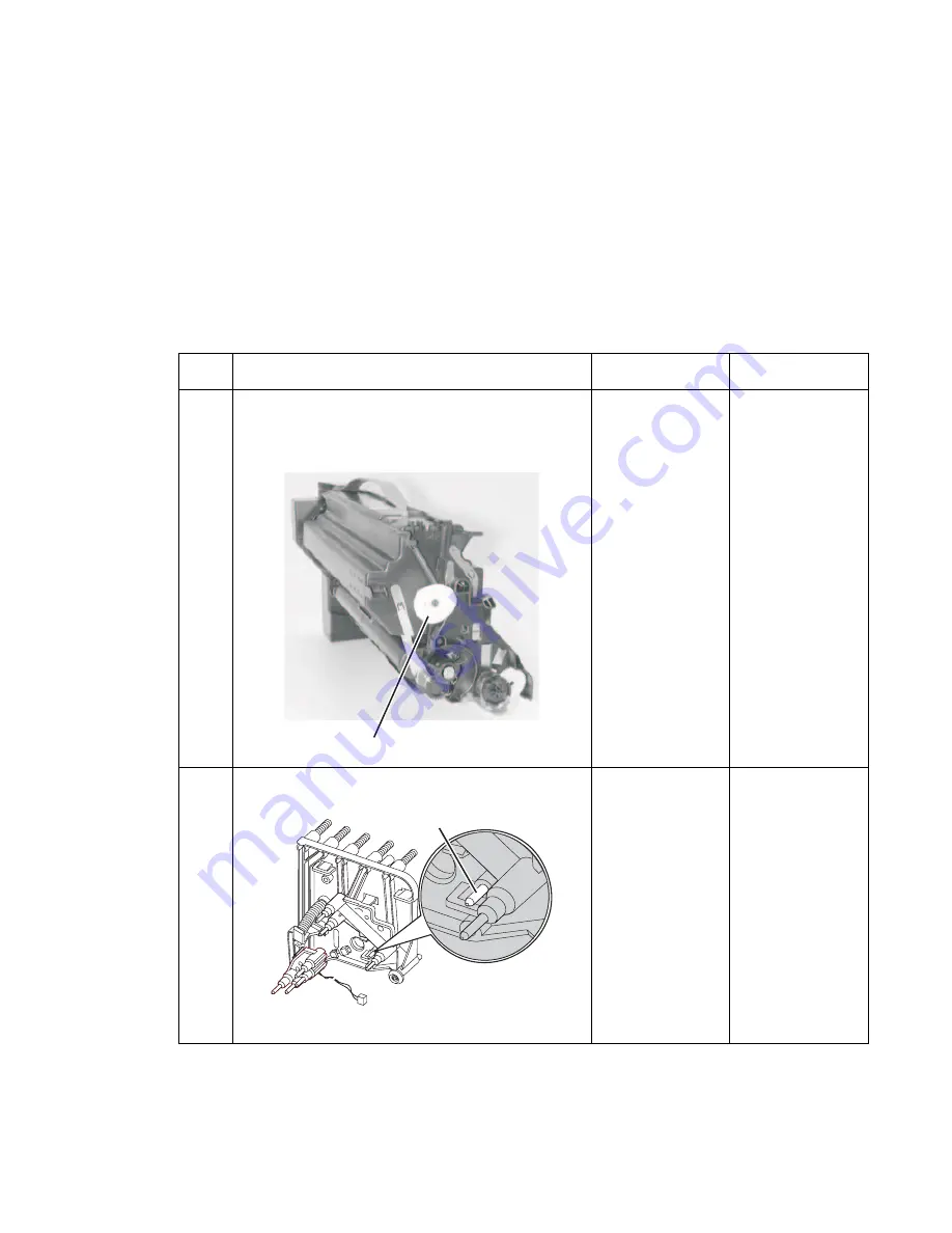
1
Check the toner metering cam (A) on the rear of the
black cartridge.
Note:
In some cartridges the toner metering cam is
black. the cam present on the cartridge?
Go to step 2
If the toner
metering cam is
not present, check
the printer to make
sure it is not inside.
Replace the
damaged
cartridge.
2
Check the TMC pin (B) in the black cartridge contact
assembly to make sure it moves freely.
Does the pin move freely?
Go to step 3
Replace the
cartridge contact
assembly.
A
B
Содержание 13P0195 - C 750dn Color Laser Printer
Страница 14: ...xiv Service Manual 5060 00x ...
Страница 15: ...Laser notice xv 5060 00x ...
Страница 16: ...xvi Service Manual 5060 00x ...
Страница 34: ...1 14 Service Manual 5060 00x ...
Страница 115: ...Diagnostic information 2 81 5060 00x Printer configuration diagrams for 24x paper jams ...
Страница 237: ...Repair information 4 19 5060 00x 9 Remove the MPF swing arm assembly E E ...
Страница 312: ...4 94 Service Manual 5060 00x ...
Страница 313: ...Connector locations 5 1 5060 00x 5 Connector locations Locations Printer boards ...
Страница 315: ...Connector locations 5 3 5060 00x Printer sensors ...
Страница 316: ...5 4 Service Manual 5060 00x Cartridge contact assembly pin locations ...
Страница 317: ...Connector locations 5 5 5060 00x Engine board cabling ...
Страница 318: ...5 6 Service Manual 5060 00x RIP board cabling ...
Страница 344: ...5 32 Service Manual 5060 00x HCOF system board ...
Страница 350: ...7 2 Service Manual 5060 00x Assembly 1 Covers ...
Страница 352: ...7 4 Service Manual 5060 00x Assembly 1 1 Covers ...
Страница 354: ...7 6 Service Manual 5060 00x Assembly 2 Cartridge mounting ...
Страница 356: ...7 8 Service Manual 5060 00x Assembly 3 Fuser 3 2 1 ...
Страница 358: ...7 10 Service Manual 5060 00x Assembly 3 1 Fuser web oiler 1 2 3 ...
Страница 368: ...7 20 Service Manual 5060 00x Assembly 12 Multipurpose feeder MPF ...
Страница 370: ...7 22 Service Manual 5060 00x Assembly 13 500 sheet integrated tray ...
Страница 374: ...7 26 Service Manual 5060 00x Assembly 16 ITU drive assembly 2 4 1 5 3 5 ...
Страница 376: ...7 28 Service Manual 5060 00x Assembly 17 ITU loading ...
Страница 380: ...7 32 Service Manual 5060 00x Assembly 20 Cartridge drive assembly ...
Страница 382: ...7 34 Service Manual 5060 00x Assembly 21 Electronics ...
Страница 384: ...7 36 Service Manual 5060 00x Assembly 21 1 Electronics ...
Страница 388: ...7 40 Service Manual 5060 00x Assembly 21 4 Electronics ...
Страница 390: ...7 42 Service Manual 5060 00x Assembly 22 Electronic cabling engine board ...
Страница 392: ...7 44 Service Manual 5060 00x Assembly 23 Electronic cabling RIP board ...
Страница 396: ...7 48 Service Manual 5060 00x Assembly 26 Output expander ...
Страница 398: ...7 50 Service Manual 5060 00x Assembly 26 1 Output expander ...
Страница 400: ...7 52 Service Manual 5060 00x Assembly 27 5 bin mailbox ...
Страница 402: ...7 54 Service Manual 5060 00x Assembly 27 1 5 bin mailbox ...
Страница 404: ...7 56 Service Manual 5060 00x Assembly 28 500 sheet drawer option ...
Страница 406: ...7 58 Service Manual 5060 00x Assembly 28 1 500 sheet tray option ...
Страница 408: ...7 60 Service Manual 5060 00x Assembly 29 Duplex option ...
Страница 410: ...7 62 Service Manual 5060 00x Assembly 29 1 Duplex option ...
Страница 412: ...7 64 Service Manual 5060 00x Assembly 30 High capacity input tray HCIT ...
Страница 414: ...7 66 Service Manual 5060 00x Assembly 30 1 High capacity input tray HCIT ...
Страница 416: ...7 68 Service Manual 5060 00x Assembly 31 High capacity output finisher HCOF ...
Страница 418: ...7 70 Service Manual 5060 00x Assembly 31 1 High capacity output finisher ...
Страница 420: ...7 72 Service Manual 5060 00x Assembly 31 2 High capacity output finisher ...
Страница 422: ...Service Manual 5060 0xx Assembly 32 High capacity output finisher cables ...
Страница 426: ...7 78 Service Manual 5060 00x ...
Страница 456: ...A 30 Service Manual 5060 00x ...
Страница 458: ...B 2 Service Manual 5060 00x Print Menus Page two of two ...
Страница 459: ...Appendix B Print quality samples B 3 5060 00x Print tests Print Quality Pages Title page total of five ...
Страница 460: ...B 4 Service Manual 5060 00x Print Quality Pages Page 1 total of five ...
Страница 461: ...Appendix B Print quality samples B 5 5060 00x Print Quality Pages Page 2 total of five ...
Страница 462: ...B 6 Service Manual 5060 00x Print Quality Pages Page 3 total of five ...
Страница 463: ...Appendix B Print quality samples B 7 5060 00x Print Quality Pages Page 4 total of five ...
Страница 464: ...B 8 Service Manual 5060 00x Registration Quick Test ...
Страница 465: ...Appendix B Print quality samples B 9 5060 00x Alignment test pages Printhead alignment test pages magenta one of three ...
Страница 466: ...B 10 Service Manual 5060 00x Printhead alignment test page yellow two of three ...
Страница 467: ...Appendix B Print quality samples B 11 5060 00x Printhead alignment test page cyan three of three ...
Страница 468: ...B 12 Service Manual 5060 00x Print Line Len page ...
Страница 487: ......
Страница 488: ......
Страница 489: ......
Страница 490: ......


