background image

Setup

Lexicon

3-76

LIVE! CALIBRATION

LIVE! (Lexicon Intelligent Variable Environment) is a proprietary mode
designed to transform the way your listening room sounds. LIVE! uses a
combination of microphones and digital signal processing (DSP) to
enhance the room acoustics and create the illusion of a larger, more
reverberant listening space. Use LIVE! to create a pleasing environment
to practice or perform with a musical instrument, or to create a livelier
ambience for any social activity. LIVE! CALIBRATION must be
completed before using any of the LIVE! modes.

Notes:

You should run automatic calibration before running LIVE! CALIBRATION.
See page 3-40 for instructions on running an automatic calibration.

Any changes to the LEVELS CALIBRATION or CROSSOVER SETUP in the
SPEAKER SETUP menu will cause LIVE! to become uncalibrated.

Pressing the remote control 7/5 button will cause LIVE! to become uncalibrated.

LIVE! requires 2 microphones, available in a kit from your authorized
Lexicon dealer. (If you already own the Lexicon 4-microphone kit,
there is no need to purchase the 2-microphone kit) These microphones
should be permanently mounted in the listening room. Performing
LIVE! CALIBRATION with any microphones other than those in the kit
can produce undesirable results. 

To achieve the proper LIVE! effect your system should be configured
with a minimum of 4 speakers (Front L/R, and either side L/R or Rear
L/R). If no subwoofer is present, the crossover setting of the Front L/R
speakers should be set to FULL.

Proper microphone placement, both during calibration and when
running LIVE!, is essential to achieving the desired results. Suggested
microphone placement instructions and illustrations are included in
this section.

The location of the sound source (piano, guitar, voices, etc.) is not
critical. LIVE! will compensate for sounds that are closer to one micro-
phone or another.

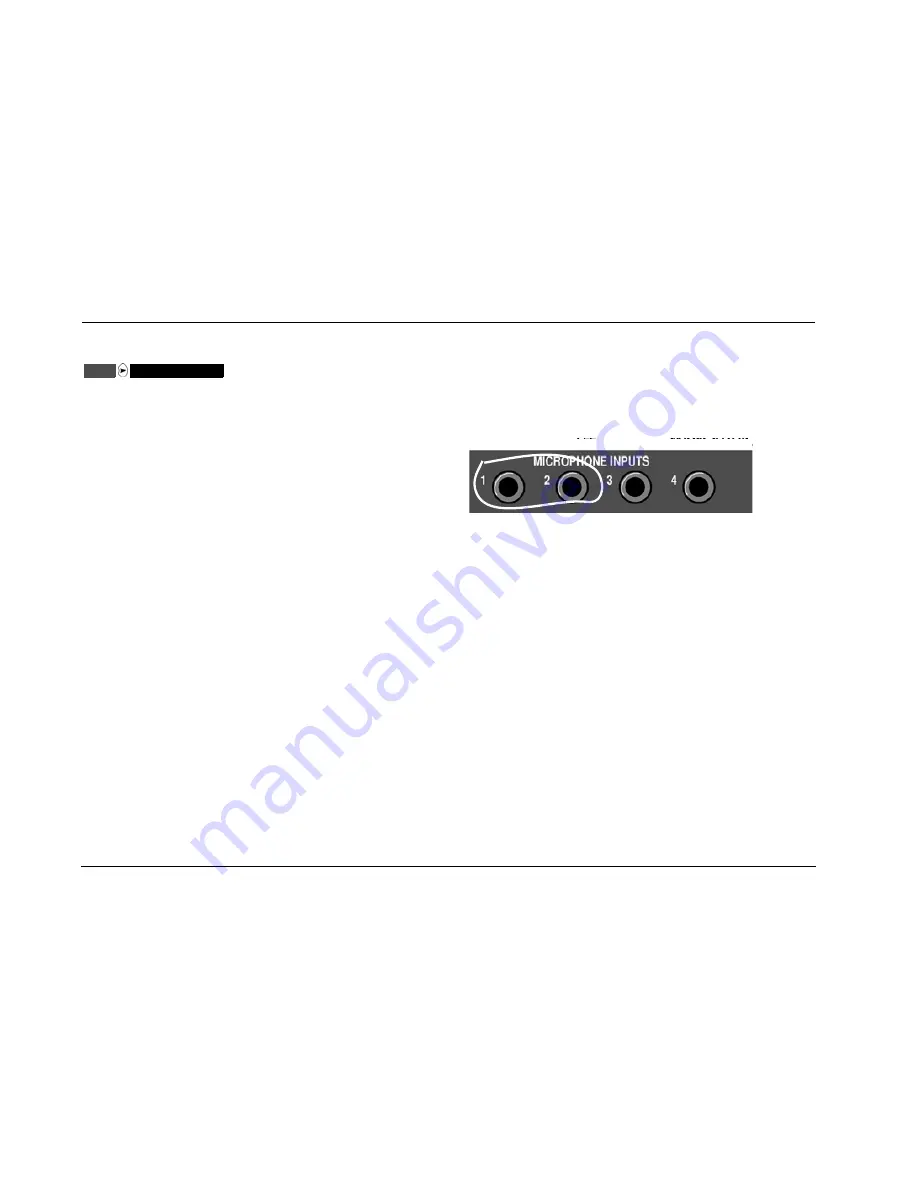
CONNECTING THE MICROPHONES

Use microphone inputs 1 and 2 on the MC-12HD rear panel

CAUTION!

The Lexicon microphones require careful handling. Dropping
or otherwise physically abusing the microphones can cause
calibration errors or irreparable damage to the microphone.

The microphone wires also require careful handling. Do not
sharply bend the wires or place objects on them.

1. Make sure the MC-12HD is powered off or in standby mode.

2. Connect the Lexicon microphones to the microphone input 1 and

2 connectors on the MC-12HD rear panel shown above. Connector
1 is for the left microphone, connector 2 is for the right.
Microphones connected to inputs 3 and 4 will be ignored during
LIVE! calibration and operation. Make sure each microphone cable
plug is fully inserted for a solid connection. 

During the microphone check, the microphones will be
referred to as 1 and 2 based on the input connector to which
the microphone is connected. You should label the micro-
phones for troubleshooting purposes.

3. Power on the MC-12HD or deactivate standby mode.

SETUP

LIVE! CALIBRATION

Содержание MC-12HD

Страница 1: ...MC 12HD Digital Controller User Guide...

Страница 2: ...r hasbeendropped Refer to the manufacturer s operating instructions for power requirements Be advised that different operating voltages may require the use of different line cord and or attachmentplug...

Страница 3: ...Other U S and foreign patents pending Ultra2 and THX are trademarks or registered trademarks of THX Ltd Surround EX is a trademark of Dolby Laboratories Used under authorization SACD is a trademark of...

Страница 4: ...the like that if not correctly performed or adhered to could result in damage or destruction to part or all of the product Calls attention to information that is essential to highlight Represents a m...

Страница 5: ...signing HDMI Audio and Video Input Connectors 3 7 Selecting Preferred Listening Modes 3 14 Configuring Advanced Input Settings 3 19 INPUT SELECT Parameter Settings 3 21 ZONE2 RECORD IN Parameter Setti...

Страница 6: ...con iv Troubleshooting Maintenance Troubleshooting 6 2 Routine Maintenance 6 4 Restoring Factory default Settings 6 5 Appendix Specifications A 2 Declaration of Conformity A 4 Menu Tree A 5 Installati...

Страница 7: ...1 Getting Started About The MC 12HD 1 2 Highlights 1 4 Product Registration 1 5 Installation Considerations 1 5 Remote Control Battery Installation 1 6...

Страница 8: ...e upgrades and backing up and restoring configuration files The other connector is reserved for possible upgrades Inside an expansion slot is available for the EQ upgrade More than just an audio and v...

Страница 9: ...tandard definition SD TV signals A composite and S video switcher accepts NTSC PAL or SECAM video signals Both switchers are designed to pass video signals without alteration or degradation In additio...

Страница 10: ...onnectors 2 composite video input connectors Broadcast quality video switching Four 32 bit DSP engines Separate DSP engine for decoding compressed audio sources LOGIC 7 decoding LIVE Lexicon Intellige...

Страница 11: ...ight DO NOT expose the MC 12HD to high temperatures humidity steam smoke dampness or excessive dust Avoid installing the MC 12HD near radiators and other heat producing appliances DO NOT install the M...

Страница 12: ...batteries 3 Align the cover over the battery compartment and gently press down until it snaps back into place The batteries should be replaced as needed Alkaline batteries which last longer without l...

Страница 13: ...eration Considerations 2 11 Main Menu 2 12 Menu Navigation 2 12 Menu Item Selection 2 12 Command Bank Activation 2 14 Command Matrix 2 15 About the Zones 2 20 Two line Status 2 20 Status Menus 2 21 St...

Страница 14: ...t the MC 12HD Balanced has a larger chassis 1 Standby Button 2 Front Panel Display 3 IR Receiver 4 Volume Knob 5 Mode and Buttons 6 Main Zone Input Selection Buttons 7 Zone 2 Input Selection Buttons 8...

Страница 15: ...zones Note When MC 12HD output levels are properly calibrated the 0dB volume level setting corresponds to the THX reference level 75dB To adjust the Main Zone volume level Rotate the volume knob cloc...

Страница 16: ...tical 5 MODE AND BUTTONS Use the Mode buttons to scroll to the previous and next available listening mode Scrolling occurs in the order shown in the MODE ADJUST menu See Mode Adjust on page 5 2 Press...

Страница 17: ...BUTTONS Selects an input in the Record Zone When an input is selected a red LED lights on the corresponding input selection button When the Record Zone is deactivated pressing a Record Zone input sele...

Страница 18: ...respond with the numbered items 1 S video Input Connectors 2 Composite Video Input Connectors 3 Component Video Input Connectors 4 HDMI Input Connectors 5 HDMI Output Connector 6 Main Video Output Con...

Страница 19: ...6 are available Note A DVI Digital Visual Interface device can be connected to the MC 12HD through a DVI to HDMI cable or adaptor DVI carries video but no audio 5 HDMI OUTPUT CONNECTOR Provides HDMI o...

Страница 20: ...udio connectors for the Main Zone and Zone 2 Otherwise both models are identical Caution Never make or break connections to the MC 12HD unless the MC 12HD and all associated components are powered off...

Страница 21: ...activate and deactivate standby mode When the MC 12HD is powered off standby mode is not available 12 AC INPUT CONNECTOR Provides power to the MC 12HD through the supplied power cord 13 RECORD ZONE AU...

Страница 22: ...d for future expansion Two connectors labeled Zone 2 L R are available in Zone 2 19 DIGITAL AUDIO INPUT CONNECTORS S PDIF AES EBU Provide digital audio input in all zones Six S PDIF coaxial RCA six S...

Страница 23: ...te the following before operating the MC 12HD remote control The remote control must be in line of sight with the front panel IR receiver Eliminate obstructions between the remote control and the IR r...

Страница 24: ...ton to open the MAIN MENU When a menu is open press the MENU button to close the menu structure When no menus are displayed press the arrow button to open the MAIN MENU When a menu is open press the a...

Страница 25: ...ting some menu parameters opens a horizontal bar graph The bar graph indicates the position the current parameter setting falls within the entire parameter range The setting appears to the right of th...

Страница 26: ...nd release a command bank selection button to activate the desired command bank The command matrix that begins on the next page indicates the commands remote control buttons perform when each command...

Страница 27: ...back light also illuminates whenever a remote control button is pressed Once illuminated the back light remains on for about 5 seconds before extinguishing 3 Activates the Main Zone command bank whic...

Страница 28: ...the PVR input for the Record Zone Increases the AUDIO CONTROLS menu TREBLE parameter in 0 5dB increments Selects the GAME input for the Main Zone Selects the GAME input for Zone 2 Selects the GAME in...

Страница 29: ...e Scrolling occurs in the order shown on the MODE ADJUST menu Activates and deactivates the trigger output connector labeled 1 when the connector is configured for remote operation Activates and deact...

Страница 30: ...parameter left and right Adjusts the AUDIO CONTROLS menu RECORD BALANCE parameter left and right Adjusts the AUDIO CONTROLS menu Main Zone BALANCE parameters left and right Scroll upward and downward...

Страница 31: ...e Reserved for possible future expansion Reserved for possible future expansion Activates the PANORAMA listening mode Selects the LOGIC 7 TV mode family for the current input source Reserved for possi...

Страница 32: ...ted in Zone 2 or the Record Zone For example if the DVD1 input is selected in the Main Zone the DVD1 input must also be selected in Zone 2 or the Record Zone The MAIN MENU SETUP INPUTS INPUT SETUP men...

Страница 33: ...splay device does not show the on screen display including the two line status The two line status displays on the component video output only when VIDEO IN is set to composite or S video and COMPONEN...

Страница 34: ...if one exists If the STATUS menu does not include a second or third page pressing and releasing the STAT button again closes the menu Note When viewing a STATUS menu on the front panel display press t...

Страница 35: ...ured for a blue screen background Green indicates low levels yellow indicates normal levels and red indicates high levels and the onset of overload Level meters appear in white when the on screen disp...

Страница 36: ...he current listening mode INPUT TYPE ANLG PCM SAMPLE RATE 44 1kHz 48kHz 88 2kHz 96kHz 2CH STATUS INPUT MODE INPUT TYPE SAMPLE RATE dB 0 6 15 30 45 R L S Parameter Possible Settings INPUT The current i...

Страница 37: ...Menu Parameter Descriptions on page 2 28 for detailed information Parameter Possible Settings INPUT The current input MODE The current listening mode CHANNELS 3 3 1 3 2 1 BIT RATE 754 5 to 1509 7kbps...

Страница 38: ...S Provides information about 2 channel analog input sources when the MAIN ADV menu ANALOG BYPASS parameter is set to ON See Status Menu Parameter Descriptions on page 2 28 for detailed information Par...

Страница 39: ...level meters Note LIVE status and 2 channel status share the 2CH STATUS menu See Status Menu Parameter Descriptions on page 2 28 for detailed information Parameter Possible Settings INPUT The current...

Страница 40: ...he digit after the slash indicates the number of surround channels present The digit after the decimal point indicates the presence of LFE low frequency effects information Possible settings for Dolby...

Страница 41: ...en the parameter setting is PCM a 2 channel digital audio source is present When the parameter setting is MIC a micro phone source is present When the parameter setting is an unknown digital audio sou...

Страница 42: ......

Страница 43: ...ttings 3 21 ZONE2 RECORD IN Parameter Settings 3 23 Speaker Setup 3 26 Setting Crossover Points 3 26 Calibrating Speaker Distances Output Levels 3 38 Speaker Calibration Parameters 3 38 Automatic Cali...

Страница 44: ...l connectors See REAR PANEL CONFIG on page 3 64 for more information DISPLAYS Opens the DISPLAY SETUP menu to customize the on screen and front panel displays restore audio video synchronization and c...

Страница 45: ...menu branch settings from accidental changes See LOCK OPTIONS on page 3 75 for more information LIVE CALIBRATION Opens the LIVE CALIBRATION menu to perform the necessary calibration before using the L...

Страница 46: ...e factory default parameter settings for each input INPUTS SETUP INPUT INPUT SETUP INPUT SETUP DVD2 LD TV SAT VCR CD PVR GAME TAPE TUNER AUX MAIN MENU MODE ADJUST AUDIO CONTROLS SETUP The DVD1 INPUT S...

Страница 47: ...d press the arrow button to advance to the next character space The cursor will automatically wrap to the first character space when the last character space is passed Note Pressing the arrow button c...

Страница 48: ...When the INPUT NAME menu opens press the remote control or buttons to highlight the RESTORE DEFAULT NAME option 3 Press the arrow button to select this option The message PRESS MENU V TO RESTORE INPUT...

Страница 49: ...to HDMI AUDIO then only HDMI video no audio is active on the HDMI output connector The received HDMI audio is processed by the MC 12HD and is available on the analog audio outputs See page 3 9 for det...

Страница 50: ...HDMI 1 to 6 S PDIF input COAX or OPTICAL HDMI audio and video S PDIF input if valid MAIN MENU MODE ADJUST AUDIO CONTROLS SETUP INPUT SETUP DVD1 DVD2 LD TV SAT VCR CD PVR GAME TAPE TUNER AUX SETUP INP...

Страница 51: ...selected an HDMI input must also be selected in the HDMI IN menu or the HDMI audio will not be available INPUTS SETUP DVD1 DIGITAL IN MAIN MENU MODE ADJUST AUDIO CONTROLS SETUP INPUT SETUP DVD1 DVD2 L...

Страница 52: ...to ANALOG INPUT SELECT menu ZONE2 IN parameter to ANLG INPUT SELECT menu RECORD IN parameter to ANLG Note LIVE cannot be selected until LIVE CALIBRATION is run When the ANALOG IN selection is LIVE no...

Страница 53: ...ls When set to ON the input levels are automatically monitored and optimized When the input signal is too high the input levels are quickly decreased to avoid overload When the input signal is too low...

Страница 54: ...rameter cannot be directly adjusted When the ANLG IN LVL menu AUTO parameter is ON the AUTO GAIN parameter indicates the amount of automatic input level adjustment When the AUTO parameter is OFF the A...

Страница 55: ...are available only when a composite video source is present S video output connectors are available when an S video or Com posite source is present COMPONENT IN COMPONENT 1 to 4 VIDEO NONE Opens the C...

Страница 56: ...a preferred listening mode for microphone sources LIVE DVD1 2 CH MODE FILM TV MUSIC MUSIC SURR PLII MOVIE PLII MUSIC PLII PRO LOGIC PL NIGHTCLUB CONCERT HALL CHURCH CATHEDRAL PANORAMA 2 CH SURROUND 2...

Страница 57: ...ening modes are listed in the table below Modes that Do Not Appear in the Input Setup menu The MC 12HD features the ability to assign preferred listening modes for each input and incoming audio format...

Страница 58: ...e selected in the SPEAKER SETUP menu and the appropriate source material is played the dynamic listening mode or mode that does not appear in the input setup menu can always be accessed using the MODE...

Страница 59: ...for 2 channel sources D Opens the DOLBY DIGITAL MODE menu to select a preferred listening mode for Dolby Digital input sources The MC 12HD activates the preferred listening mode whenever a new input i...

Страница 60: ...sent The 5 1mc THX MUSIC listening mode is used if this listening mode was activated the last time a 5 1 channel source was present Since 5 1mc THX MUSIC is a dynamic listening mode it cannot be selec...

Страница 61: ...1 MAIN ADV INPUT SELECT ANALOG BYPASS S VIDEO 16 9 S VIDEO OSD 4 3 COMPONENT OSD DIGITAL OFF AUTO ON OFF INPUT SETUP DVD1 DVD2 LD TV SAT VCR CD PVR GAME TAPE TUNER AUX DIGITAL ANALOG AUTO AUTO OFF ON...

Страница 62: ...DVANCED INPUT SELECT parameter is forced to ANALOG and ANALOG BYPASS is disabled When OFF the MC 12HD passes analog input signals through A D conversion and internal processing before passing them to...

Страница 63: ...is assigned The INPUT SETUP ANALOG IN parameter can assign an analog audio input connector for the selected input When LIVE is the selected analog input the MAIN ADVANCED INPUT SELECT parameter is fo...

Страница 64: ...CKGROUND parameter is OFF the display device using the component video output connector shows the on screen display only when composite or S video is converted and output throught the component video...

Страница 65: ...conversion before passing them to the Record Zone digital audio output connectors When no digital audio input is assigned ZONE2 IN and RECORD IN are set to ANALOG The INPUT SETUP menu ANALOG IN param...

Страница 66: ...ectors preserving the original input signal sample rate When OFF the sample rate of the digital signals is converted then passed to the Record Zone digital audio output connectors The sample rate of t...

Страница 67: ...ctors When a value is selected input signals pass through the selected value of sample rate conversion then pass to the Record Zone digital audio output connectors Set the DIG OUT RATE parameter to th...

Страница 68: ...ture expansion SETTING CROSSOVER POINTS Selecting the SPEAKER SETUP menu SET CROSSOVERS option opens the CROSSOVER SETUP menu which configures a custom or THX speaker setup Note It is important to set...

Страница 69: ...r points to speakers with the lowest crossover points Signals lower than the lowest crossover point are redirected to the subwoofer If the lowest crossover point is FULL low frequency signals excludin...

Страница 70: ...each crossover setting From left to right the curves represent crossover settings from 30Hz to 120Hz The graph above does not show the THX 80Hz crossover point which is 12dB per octave Low pass filte...

Страница 71: ...24dB per octave filter to the Subwoofer L R output connectors Notes A THX speaker setup is not required to activate THX listening modes In the THX SETUP menu only the REAR L R THX ULTRA2 SUB BGC and A...

Страница 72: ...SETUP menu When the THX ULTRA2 SUB parameter is set to OFF the BGC parameter is not available N A SPEAKERS SETUP SET CROSSOVERS CUSTOM SETUP or SPEAKERS SETUP SET CROSSOVERS THX SETUP Parameter CUSTO...

Страница 73: ...CALIBRATING MAIN MENU MODE ADJUST AUDIO CONTROLS SETUP CUSTOM SETUP FRONT L R CENTER SIDE L R REAR L R SUB XOVER 40Hz 60Hz 60Hz 60Hz 40Hz OFF OFF SUB L R N A SUB XOVER FULL 30Hz 40Hz 50Hz 60Hz 70Hz 8...

Страница 74: ...Hz to 120Hz THX 80Hz NONE Assigns a crossover point for the Main Zone audio output connector labeled SIDE L R when a custom speaker setup is selected Opens the SIDE L R SPEAKERS menu to select a cross...

Страница 75: ...o activate and deactivate the REAR L R output connectors Select THX 80Hz to activate and configure the Rear L R output connectors for a 7 1 channel THX speaker setup Select NONE to deactivate the Rear...

Страница 76: ...s are configured for a speaker setup that includes one subwoofer and the SUB L R parameter cannot be adjusted SUB XOVER FULL 30 to 120Hz THX 80Hz Assigns a crossover point for the Main Zone audio outp...

Страница 77: ...SETUP THX SPEAKER SETUP CAUTION PRESSING THE BUTTON WILL AUTOMATICALLY CHANGE THE OUTPUTS TO A THX SPEAKER CONFIGURATION CUSTOM SETUP FRONT L R CENTER SIDE L R REAR L R SUB XOVER 80Hz 80Hz 80Hz 80Hz 8...

Страница 78: ...ra2 listening modes including THX UL2Cin THX MUSIC DTS THX UL2Cin DTS THX MUSIC 5 1mc THX UL2Cin and 5 1mc THX MUSIC Applied to film sources ASA processing blends surround channel signals to optimize...

Страница 79: ...nel playback When you use the 7 5 button the MC 12HD automatically Activates ASA processing during 7 channel playback Deactivates ASA processing during 5 channel playback Switches between the 5 1 THX...

Страница 80: ...microphones or SPL meter and the speakers Note If power is lost during automatic calibration of speaker levels or speaker distances re calibration of speaker levels and speaker distances is required...

Страница 81: ...aker setup the corresponding speaker distance or output level parameter is not available N A Speaker Distance Settings Output Level Settings Parameter Default Setting Possible Setting Default Setting...

Страница 82: ...ers accurate calibration with minimal interaction automatically applying calibrated speaker distances and output levels Calibrates speaker distances within 0 5 foot 2m of the physical distance between...

Страница 83: ...in the kit will produce unpredictable results Proper microphone placement is essential to achieving the desired automatic calibration results Pay particular attention to the microphone placement inst...

Страница 84: ...ght speakers 3 In a clear line of sight path with the speakers 3 In a location unobstructed by furniture and other fixtures where echoes will not obscure calibration noise signals 3 At least 2 feet 0...

Страница 85: ...her fixtures where echoes might obscure calibration noise signals 7 Position the microphones within 2 feet 0 61m of speakers and walls or more than 30 feet 9 14m from any one speaker The illustration...

Страница 86: ...ECK MICROPHONES screen opens in the on screen display indicating the importance of proper microphone placement to achieve accurate automatic calibration results 3 Press the arrow button to begin the m...

Страница 87: ...ore detailed results for the selected microphone A message similar to the one shown at the bottom of the previous column opens in the on screen display Refer to the table on the next page for informat...

Страница 88: ...t connections to ensure that the microphones are properly con nected to the MC 12HD and that microphone cable plugs are fully inserted for a solid connec tion The microphones might be positioned too f...

Страница 89: ...ion noise signals 3 At least 2 feet 0 61m from all speakers and walls but within 30 feet 9 14m of all speakers The illustration to the right provides an example of proper microphone placement when cal...

Страница 90: ...ers and walls but within 30 feet 9 14m of all speakers The illustration to the right provides an example of proper microphone placement when calibrating for multiple listening positions in a single ro...

Страница 91: ...thin 30 feet 9 14m of all speakers The illustration to the right provides an example of proper microphone placement when calibrating for multiple listening positions in multiple rows Each microphone i...

Страница 92: ...kers 7 Position the microphones on the floor on seat cushions or in locations obstructed by furniture and other fixtures where echoes might obscure calibration noise signals 7 Position the microphones...

Страница 93: ...cted by furniture and other fixtures where echoes might obscure calibration noise signals 7 Position the microphones within 2 feet 0 61m of speakers and walls or more than 30 feet 9 14m from any one s...

Страница 94: ...r more information about automatic calibration options If a microphone check is unsuccessful one of the error messages shown at the right appears on the on screen display indicating that a successful...

Страница 95: ...screen The cursor automatically scrolls downward through speaker calibration parameters highlighting each param eter while the MC 12HD calculates a distance for the corresponding speaker As it finishe...

Страница 96: ...at least one error occurred during calibration Press the or arrow button to high light the desired calibration procedure DISTANCES displays the AUTO DIS TANCES screen shown in the left column of this...

Страница 97: ...er levels 1 Press the arrow button to return to the SET LEVELS menu Press the and arrow buttons to toggle between calibrated output levels AUTO and original output levels The speaker graphics at the b...

Страница 98: ...libra tion noise signals or the MC 12HD could not calculate a value Refer to the microphone placement examples on pages 3 42 to 3 46 to confirm that the microphones are appropriately positioned for au...

Страница 99: ...such as an audio calibration disc Activates an appropriate listening mode based on the current Main Zone input source BASS PEAK LIMITERS Provides amplitude limits for low frequency signals sent to the...

Страница 100: ...ter is selected measure the distance between the primary listening position and the front of the front left speaker connected to the Main Zone audio output connector labeled Front L 4 When the speaker...

Страница 101: ...p cannot be adjusted during the internal noise test These output levels can be adjusted during the external noise test but there is no need to do so SPEAKERS SETUP MANUAL LEVELS CALIBRATION INTERNAL N...

Страница 102: ...el while the test is in progress to achieve THX reference levels 75dB INTERNAL NOISE TEST LEVELS CALIBRATION MANUAL SPEAKERS SETUP To manually calibrate output levels during the internal noise test 1...

Страница 103: ...ending on the current input source speaker setup and parameter settings Refer to the Listening Mode Descriptions section beginning on page 5 5 for more information Note When the external noise test be...

Страница 104: ...quency signals Note You should configure BASS PEAK LIMITERS menu parameter settings whether output levels are automatically or manually calibrated SPEAKERS SETUP MANUAL LEVELS CALIBRATION BASS PEAK LI...

Страница 105: ...striction applied to the Subwoofer L R output connectors and to other Main Zone audio output connectors to which low frequency signals are redirected To set the L R LIMIT ADJ parameter 1 Select the L...

Страница 106: ...d one 5 1 channel configuration Front L R Center Subwoofer Side L R 8 STEREO INPUTS Select the 8 STEREO INPUTS option to configure the analog audio input connectors as eight stereo connectors When 8 S...

Страница 107: ...nfigured as stereo connectors The analog audio input connectors labeled 6 7 and 8 are configured as 5 1 channel connectors Input sources that were assigned to the stereo connectors labeled 6 7 and 8 a...

Страница 108: ...When ON is selected the custom unit name scrolls across the on screen and front panel displays whenever the MC 12HD is activated When OFF is selected the custom unit name does not scroll across the on...

Страница 109: ...ss the or arrow button to change the character above the cursor Press the button to advance to the next character space The cursor will automatically wrap to the first character space when the last tw...

Страница 110: ...el display as a guide to reset the ON SCREEN DISPLAY menu STATUS parameter to ALWAYS ON or 2 SECONDS POSITION TOP CENTER BOTTOM Controls the vertical alignment of the two line status on the display de...

Страница 111: ...ally deactivates when the display device is connected to the Main Zone component video output connector REMOTE STATE ON OFF Activates the remote control command bank indicator a letter that appears in...

Страница 112: ...or 2 SECONDS BRIGHTNESS 100 75 50 25 Controls the illumination of front panel display characters When a setting is selected front panel display characters automatically adjust to the selected illumin...

Страница 113: ...te button is pressed ZONE PWR ON LAST LVL 80 to 12dB Sets the Zone 2 volume level for the output connector labeled Var to the selected value when Zone 2 is activated When a value is selected the Zone...

Страница 114: ...olume level that was selected in the Record Zone during the previous operating session When the Record Zone Var audio output connector is connected to a recording device set the volume to 0dB to achie...

Страница 115: ...ram operation parameters Parameter Default Setting Possible Settings REMOTE ONLY ON ON OFF Program Operation OFF ON OFF SETUP TRIGGERS MAIN MENU MODE ADJUST AUDIO CONTROLS SETUP TRIGGER SETUP TRIGGER...

Страница 116: ...lected trigger output connector for program operation when the REMOTE ONLY parameter is set to OFF Select the ON setting to associate the selected connector with the corre sponding input s or listenin...

Страница 117: ...ted SETUP menu branch settings can be adjusted Note the following When the MODES parameter is set to LOCKED the up and down arrows can still be used to adjust subwoofer output levels applied to the se...

Страница 118: ...R and either side L R or Rear L R If no subwoofer is present the crossover setting of the Front L R speakers should be set to FULL Proper microphone placement both during calibration and when running...

Страница 119: ...nd side speakers 3 At an approximate height between the waist and head of a standing person 3 In a location unobstructed by furniture and other fixtures 3 At least 2 feet 0 61m from all speakers Note...

Страница 120: ...the microphones on the front or rear walls 7 Place the microphones near the floor or ceiling 7 Obstruct the microphones with furniture or other fixtures 7 Place the microphones within 2 feet 0 61m of...

Страница 121: ...bration procedure completed with no errors SIGNAL TOO LOW Indicates that the microphones failed to pick up sufficient cali bration noise signals for calibration to complete After reading the message p...

Страница 122: ......

Страница 123: ...4 Audio Controls Audio Controls 4 2...

Страница 124: ...output connectors including all Record Zone inputs Note When LIVE is active the BASS TREBLE TILT EQ and LOUDNESS controls do not function and the corresponding parameters are shown in the AUDIO CONTR...

Страница 125: ...rol the bass from the remote control Press the Shift button Press the CD button to increase the BASS parameter setting in 0 5dB increments Press the TAPE button to decrease the BASS parameter setting...

Страница 126: ...ol the treble from the remote control Press the Shift button Press the PVR button to increase the TREBLE parameter setting in 0 5dB increments Press the TUNER button to decrease the TREBLE parameter s...

Страница 127: ...le frequencies lower than 1kHz are simultaneously boosted The graph shown at the right indicates the frequency response of all TILT EQ parameter settings To control the tilt EQ from the remote control...

Страница 128: ...ed to THX reference levels When OFF is selected no loudness compensation is applied The graph shown at the right indicates the frequency response that is automatically applied when the LOUDNESS parame...

Страница 129: ...Main Zone fader Press the or arrow buttons to adjust the Main Zone fader backward and forward ZONE2 BALANCE L R Controls the left to right balance of the Zone 2 audio output connectors To control the...

Страница 130: ......

Страница 131: ...ode Activation 5 2 Preferred Listening Mode Selection Parameters 5 3 Mode Buttons 5 4 Mode Family Selection Buttons 5 4 Listening Modes Descriptions 5 5 Listening Mode Menu Option Parameter Descriptio...

Страница 132: ...tically activates a listening mode in response to certain commands For this reason it is important to understand the three methods through which listening mode activation occurs Listening modes activa...

Страница 133: ...urce is present the 5 1 L7 MUSIC listening mode is activated If the DVD1 input is then selected to play a DTS ES source the DTS or DTS ES L7 FILM listening mode is activated Note Refer to the Selectin...

Страница 134: ...e L7 FILM listening mode The table below indicates the listening modes associated with each mode family selection button Input Source Button 2 Channel 5 1 Dolby Digital DTS ES 5 1mc DOLBY PLII THX THX...

Страница 135: ...ders See Listening Mode Menu Option Parameter Descriptions on page 5 37 TV This listening mode is designed for playback of 2 channel stereo or matrix encoded television broadcast sources LOGIC 7 TV is...

Страница 136: ...sounds from the input source and sends these sounds to all speakers Ambient sounds are heard from all directions creating a realistic playback presentation that simulates what listeners experience in...

Страница 137: ...e 5 37 for detailed descriptions PLIIx MOV PLII MOVIE The Dolby PLIIx MOV MOVIE and Dolby PLII MOVIE listening modes are designed to playback 7 1 PLIIx or 5 1 PLII discrete channels decoded from 2 cha...

Страница 138: ...e mono surround channel with a high frequency rolloff above 7kHz This mode is recommended for home theaters with THX certified speakers Dolby PL THX mode Applies THX re equalization to simulate high f...

Страница 139: ...DTS NEO 6 derives six channels when both side and rear speakers are present rear channels will be in parallel It derives five channels when only side or rear speakers are present In addition to THX p...

Страница 140: ...ources The DTS Neo 6 MUSIC listening mode can be activated with the front panel or remote control Mode buttons The DTS Neo 6 CIN listening mode can also activated with the remote control DTS button wh...

Страница 141: ...orithm inherited from Lexicon professional products BASS RT MID RT and SIZE parameter settings are interdependent meaning that the full parameter range might not be available depending on the other pa...

Страница 142: ...stereo field with greater depth Sound quality depends on proper location of the listening position and front speakers When the front speakers are positioned close to either side of the display device...

Страница 143: ...page Otherwise the PANORAMA listening mode will be calibrated with varying results An external calibration source is required to calibrate the PANORAMA listening mode You should select a familiar ste...

Страница 144: ...ORAMA CALIBRATION LISTENER POS parameter to compensate for the difference using the remote control or arrow button Each increment within the 127 to 127 parameter range represents about one third of an...

Страница 145: ...LOGIC This mode designed for playback of mono sources uses proprietary Lexicon reverb algorithms to realistically expand mono sources to use all channels This dramatically increases the perceived wid...

Страница 146: ...ont steering When both side and rear speakers are present the 5 1 L7 FILM listening mode also increases the perceived length and sense of envelopment of the listening space See Listening Mode Menu Opt...

Страница 147: ...etailed descriptions Parameter Default Setting Possible Settings VOCAL ENHANCE 0 0dB 6 0dB 3 0dB 0 0dB FRONT STEERING FILM OFF MSURR MUSIC FILM RE EQUALIZER OFF OFF ON SOUND STAGE REAR REAR NEUTRAL FR...

Страница 148: ...decoding is engaged when the SURROUND EX parameter is set to OFF or AUTO and a non flagged 5 1 channel Dolby Digital source with or without THX Surround EX encoding is detected The THX SurEX listenin...

Страница 149: ...eakers are present ASA processing is applied to signals sent to the rear speakers Refer to the ASA parameter description on page 3 36 for more information For best results place the rear speakers clos...

Страница 150: ...ed from 5 1 channel Dolby Digital music sources The 5 1 PLIIx MUSIC listening mode can also be used with other types of Dolby Digital sources with mixed results The seven main channels are full freque...

Страница 151: ...from the other surround channels Dolby Digital Surround EX decoding is activated when the EX DECODING parameter is set to ON or AUTO and a flagged 5 1 channel Dolby Digital source recorded with Dolby...

Страница 152: ...subwoofer See Listening Mode Menu Option Parameter Descriptions on page 5 37 for detailed descriptions Parameter Default Setting Possible Settings EX DECODING AUTO AUTO ON OFF COMPRESSION OFF AUTO ON...

Страница 153: ...SURR This listening mode designed for playback of Dolby Digital Encoded mono sources sends mono signals to all channels See Listening Mode Menu Option Parameter Descriptions on page 5 37 for detailed...

Страница 154: ...and the ES DECODING parameter is set to ON or AUTO and a 5 1 channel matrix encoded source is detected DTS ES Discrete decoding is activated when both the side and rear speakers are present and the E...

Страница 155: ...designed for enhanced playback of 5 1 channel DTS 5 1 channel matrix encoded DTS ES or 6 1 channel discrete encoded DTS ES music sources The listening mode name differs depending on the encoding pres...

Страница 156: ...ault or OFF When the ES DECODING parameter is set to OFF the DTS THX ULTRA2 listening mode is always active When the parameter is set to AUTO the DTS THX ULTRA2 listening mode activates when a 5 1 cha...

Страница 157: ...l discrete encoded DTS ES sources The listening mode name differs depending on the encoding present in the input source the DECODING parameter setting and the speaker setup Refer to page 5 24 for more...

Страница 158: ...ance calibration and audio controls tone controls See Listening Mode Menu Option Parameter Descriptions on page 5 37 for detailed descriptions Option Parameter Default Setting Possible Settings CENTER...

Страница 159: ...ters and might sound too bright when played back in home theaters without re equalization THX timbre matching to minimize timbre differences between the front and surround channels which results in sm...

Страница 160: ...tion The 5 1mc THX SurEX listening mode The 5 1mc THX SurEX listening mode is available when both side and rear speakers are present and THX surround EX decoding is active THX Surround EX decoding is...

Страница 161: ...ol Mode buttons 5 1mc STANDARD This mode allows 5 1 channel sources to use bass management speaker crossovers speaker distance calibration and audio controls tone controls When these features are not...

Страница 162: ...hannel speaker setup set the OUTPUT LEVELS menu SIDE L R or REAR L R parameter to OFF to deactivate the associated surround speakers The 5 1mc BYPASS listening mode is automatically activated whenever...

Страница 163: ...gent Variable Environment is a proprietary mode designed to transform the way your listening room sounds It provides a realistic illusion of a larger more reverberant listening space LIVE SMALL simula...

Страница 164: ...VE MED ADVANCED parameter settings Parameter Default Setting Possible Settings REVERB LVL 4dB 80dB to 0dB EARLY RFLX LVL 14dB 80dB to 12dB BASS XOVER 156Hz 30Hz to 19 9kHz OFF LIVE SMALL MODE ADJUST L...

Страница 165: ...ning between the custom and factory default versions of the selected listening mode When PRESET is selected the listening mode is heard in its factory default condition as if all listening mode menu p...

Страница 166: ...parameters to their factory default settings To restore the factory default version of the selected listening mode 1 Follow the RESET MODE menu path to select the RESET MODE option The PRESS RIGHT V T...

Страница 167: ...es BASS CONTENT BINAURAL MONO STEREO Adjusts the bass content of binaural mono and stereo recordings When set to BINAURAL low frequency compensation is activated Select this setting for true binaural...

Страница 168: ...When OFF compression is not applied Set this parameter to AUTO or ON for Dolby Digital input sources that are listened to at lower volume levels especially for nighttime viewing to avoid disturbing ot...

Страница 169: ...TATUS menu includes an SB level meter when the ES DECODING parameter is set to ON and a 5 1 channel DTS source is present or when the ES DECODING parameter is set to AUTO and a 5 1 channel matrix enco...

Страница 170: ...hannel imbalance Available in PANORAMA mode LFE OFF 30 0 to 012dB Controls the output level of the Main Zone audio output connector labeled LFE The OUTPUT LEVELS menu does not include the LFE paramete...

Страница 171: ...RT or SIZE parameters to a high value may produce undesirable or damaging audio OUTPUT LEVELS Opens the OUTPUT LEVELS menu which is used to adjust output levels for the Main Zone audio output connecto...

Страница 172: ...5 1 MONO DTS ES 2 CHAN 5 1mc 2 CHANNEL 2CH BYPASS and LIVE modes RESET MODE Restores the factory default version of the selected listening mode restoring all listening mode menu parameters to their f...

Страница 173: ...the setting closest to the angle between the front left and right speakers and the primary listening position Refer to the Calibration section that begins on page 5 13 for more information about the S...

Страница 174: ...Surround EX decoding is engaged THX or THX ULTRA2 listening modes are available when THX Surround EX decoding is not engaged Refer to the 5 1 THX ULTRA2 5 1 THX SurEX 5 1 THX listening mode descripti...

Страница 175: ...ls the level of dialog boost in the audio output connector labeled Center Increase this setting to improve dialog intelligibility particularly at lower volume levels Available in all Logic 7 modes MOD...

Страница 176: ...modes EFFECT LVL NIGHTCLUB CONCERT HALL CHURCH CATHEDRAL PANORAMA MONO LOGIC and 5 1 MONO LOGIC ES DECODING All DTS modes EX DECODING 5 1 PLIIx MOV 5 1 PLIIx MUS DOLBY DIGITAL EX and DOLBY DIGITAL FRO...

Страница 177: ...M 5 1 L7 TV THX ULTRA2 THX SurEX THX DTS ES L7 FILM DTS ES THX ULTRA2 DTS ES THX 5 1mc L7 FILM 5 1mc THX ULTRA2 5 1mc THX SurEX 5 1mc THX REAR DLY OFFSET All L7 modes and PANORAMA REAR L R All except...

Страница 178: ...H and CATHEDRAL SPREAD All LIVE modes SUB L R SUB L R LVL All except LIVE modes SURR ROLLOFF All L7 modes SURROUND DLY DPLII MUSIC and DPLIIx MUSIC SURROUND EX THX ULTRA2 THX SurEX THX SURROUND MIX 5...

Страница 179: ...6 Troubleshooting Maintenance Troubleshooting 6 2 Routine Maintenance 6 4 Restoring Factory default Settings 6 5...

Страница 180: ...uctions that begin on page 2 21 to open the STATUS menu for the current input source 4 Make sure the audio is not muted The message MUTE ON or FULL MUTE ON appears in the on screen and front panel dis...

Страница 181: ...iated component 2 Check the INPUT SETUP menu HDMI IN VIDEO IN and COMPONENT IN parameters to ensure the appropriate video connector is assigned to the selected input 3 The currently selected source or...

Страница 182: ...ebase at http www lexicon com kbase for answers to frequently asked questions and additional troubleshooting information ROUTINE MAINTENANCE The bulleted items below describe routine maintenance that...

Страница 183: ...standby mode is activated press the Standby Button again then quickly press and hold the Mute button until the FACTORY SETTINGS menu shown above opens on the on screen and front panel displays Note Th...

Страница 184: ......

Страница 185: ...A Appendix Specifications A 2 Declaration of Conformity A 4 Menu Tree A 5 Installation Worksheet A 20...

Страница 186: ...ctors 1 S PDIF coaxial RCA and 1 S PDIF optical connector in parallel Main Zone Audio Performance A D Conversion 24 bit 96kHz dual bit architecture D A Conversion 24 bit 44 1 to 192kHz multi bit archi...

Страница 187: ...Compatibility 3 channel Y Pr Pb format independent Switching Passive Impedance 75 Insertion Loss 3dB Bandwidth 250MHz Microphone Input Connectors Inputs 4 3 5 miniature phone jacks Input Sensitivity 1...

Страница 188: ...Standard s to Which Conformity is Declared EN55013 2001 EN55020 2002 EN61000 3 2 2000 EN61000 3 3 2001 and EN60065 2002 Manufacturer Harman Specialty Group 3 Oak Park Bedford MA 01730 1413 USA The equ...

Страница 189: ...SETUP menu Shown at the far right The parameters on the left side of the TRIGGER SETUP menu are identical regardless of the selected connector The TRIGGER SETUP menu indicates factory default paramet...

Страница 190: ...IGITAL IN HDMI AUDIO ANALOG IN ANALOG 3 ANLG IN LVL AUTO VIDEO IN NONE COMPONENT IN 4 2 CH TV D 5 1 TV FILM 5 1mc 5 1mc FILM MIC LIVE MED MAIN ADVANCED ZONE2 IN DMIX RECORD IN DMIX RECORD ADVANCED VCR...

Страница 191: ...ANLG DMIX DVD1 RECORD ADV ANLG IN LVL DIGITAL BYPASS DIG OUT RATE RECORD DIGITAL OFF 44 1kHz ENABLED DIGITAL ANALOG AUTO AUTO OFF NORMAL FAST BLOCKED ENABLED INPUT 96kHz 88 2kHz 48kHz 44 1kHz 18 to 12...

Страница 192: ...G BYPASS S VIDEO 16 9 S VIDEO OSD 4 3 COMPONENT OSD DIGITAL OFF AUTO ON OFF HDMI OSD ON FORMAT DETECT NORMAL SAT MAIN ADV INPUT SELECT ANALOG BYPASS S VIDEO 16 9 S VIDEO OSD 4 3 COMPONENT OSD DIGITAL...

Страница 193: ...ANLG IN LVL DIGITAL BYPASS DIG OUT RATE RECORD OdB OFF 44 1kHz ENABLED LD RECORD ADV ANLG IN LVL DIGITAL BYPASS DIG OUT RATE RECORD OdB OFF 44 1kHz ENABLED DVD1 RECORD ADV ANLG IN LVL DIGITAL BYPASS...

Страница 194: ...AUTOMATICALLY CHANGE THE OUTPUTS TO A THX SPEAKER CONFIGURATION THX SETUP FRONT L R CENTER SIDE L R REAR L R SUB XOVER THX 80Hz THX 80Hz THX 80Hz THX 80Hz THX 80Hz OFF OFF SUB L R N A LFE ULTRA2 SUB...

Страница 195: ...STANCES OUTPUT LEVELS AROUND PREFERRED LISTENING POSITIONS SPEAKER SETUP SET CROSSOVERS CHECK MICROPHONES AUTOMATIC MANUAL SET CROSSOVERS BEFORE CALIBRATING CHECK MICROPHONES MIC 1 MIC 2 MIC 3 MIC 4 P...

Страница 196: ...SETUP DISTANCES LEVELS AUTO VALUES APPLIED PRESS TO VIEW DETAILS OK OK ERROR ERROR OK LEVELS OK DISTANCES OK SPEAKER SPKR OUTPUT TOO HIGH SPEAKER SPKR OUTPUT TOO LOW SPEAKER SPEAKER IS NOT ENABLED SP...

Страница 197: ...0 0dB 0 0dB 0 0dB 0 0dB 0 0dB 0 0dB 0 0dB 0 0dB N A N A SPKR OUTPUT TOO HIGH SPEAKER SPKR OUTPUT TOO LOW SPEAKER SPEAKER IS NOT ENABLED SPEAKER FRONT LEFT CENTER FRONT RIGHT SIDE RIGHT REAR RIGHT REAR...

Страница 198: ...40Hz 40Hz 60Hz 60Hz LEVELS CALIBRATION INTERNAL NOISE TEST EXTERNAL NOISE TEST BASS PEAK LIMITER 18 to 12dB BASS PEAK LIMITER CAL NOISE L R LIMITER L R LIMIT ADJ CAUTION HIGH AUDIO LEVELS ON ON 100dB...

Страница 199: ...LIBRATION DONE LIVE CALIBRATION TO LEAVE THE ROOM OR SIT QUIETLY PRESS TO BEGIN COUNTDOWN LIVE CALIBRATION PRESS TO CONTINUE SIGNAL TOO LOW ON OFF MAIN MENU MODE ADJUST AUDIO CONTROLS SETUP AUDIO CONT...

Страница 200: ...LEVELS PLIIx OUTPUT LEVELS CUSTOM MUSIC NIGHTCLUB CENTER DEPTH SIZE PRE DELAY ROLLOFF EFFECT LVL OUTPUT LEVELS CUSTOM LIVENESS 11 5m 196ms SPEECH DETECT ON 5ms 9 0kHz 3dB CONCERT HALL CENTER DEPTH SI...

Страница 201: ...E MID RT 4 71s BASS RT 4 71s ROLLOFF 3 1kHz TREB CUT RT 2 4kHz PRE DELAY 20ms ADVANCED CUSTOM 5 1 FILM VOCAL ENHANCE 0 0dB RE EQUALIZER ON SOUND STAGE REAR 5 SPKR ENHANCE ON BASS ENHANCE OFF SURR ROLL...

Страница 202: ...CE SPEAKER ANGLE LISTENER POS NOTE ENSURE THAT SPEAKER SETUP HAS BEEN PERFORMED LEFT RIGHT 30deg 0 PANORAMA EFFECT LVL 4dB STEREO 0 3 1kHz 15ms I BASS CONTENT LOW FREQ WIDTH SURR ROLLOFF REAR DLY OFFS...

Страница 203: ...INPUT BALANCE 6 0dB 3 0dB 0 0dB SOURCE RIGHT LEFT RIGHT LEFT SOUND STAGE FRONT NEUTRAL REAR ROLLOFF REAR DLY OFFSET PANORAMA ON OFF RE EQUALIZER ON OFF MID RT MASTER LEVEL LOW FREQ WIDTH LIVENESS L l...

Страница 204: ...nformation dB 0 6 15 30 45 R L 2CH STATUS S INPUT MODE INPUT TYPE SAMPLE RATE dB 0 6 15 30 45 R L C SL SR LFE SAMPLE RATE HDMI STATUS S HDMI CONNECTOR VID FMT VERT RATE AUD IN AUDIO FMT CHANNELS SAMPL...

Страница 205: ...CD PVR GAME TAPE TUNER AUX NAME HDMI IN DIGITAL IN ANALOG IN ANLG IN LVL VIDEO IN COMPONENT IN 2 CH D 5 1mc MIC MAIN ADVANCED INPUT SELECT ANALOG BYPASS S VIDEO 16 9 S VIDEO 4 3 OSD COMPONENT OSD ZON...

Страница 206: ...R THX 80Hz LFE OFF OUTPUT LEVEL DISTANCE FRONT LEFT CENTER FRONT RIGHT SIDE RIGHT REAR RIGHT REAR LEFT SIDE LEFT SUB LEFT SUB RIGHT LFE SETTING ULTRA2SUB BGC ASA CAL NOISE L R LIMITER L R LIMIT ADJ LF...

Страница 207: ...NDARD 5 1mc 2 CHAN 5 1a BYPASS 2CH BYPASS LIVE SMALL LIVE MED LIVE LARGE REMOTE ONLY DVD1 DVD2 LD TV SAT VCR CD PVR GAME TAPE TUNER AUX ZONE2 INPUTS RECORD INPUTS FILM TV MUSIC MUSIC SURR PLIIx PLIIx...

Страница 208: ......

Страница 209: ...meter 2 28 AUDIO CNTRL parameter 3 75 AUDIO CONTROLS menu 4 2 audio input connectors 2 7 audio output connectors 2 7 2 9 AUTO AZIMUTH parameter 5 37 AUTO GAIN parameter 3 12 automatic calibration 3 40...

Страница 210: ...listening mode 5 27 DTS Neo 6 CIN listening mode 5 4 5 10 DTS Neo 6 MUSIC listening mode 5 10 5 14 DTS STATUS menu 2 25 DTS THX MUSIC listening mode 5 27 DTS THX UL2 Cin listening mode 5 26 DTS ES L7...

Страница 211: ...ck 5 SPKR ENHANCE 5 37 LOUDNESS parameter 4 2 4 6 LOW FREQ WIDTH parameter 5 12 5 41 M MAIN ADVANCED parameter 3 19 MAIN PWR ON parameter 3 71 main zone about 2 20 advanced menu 3 19 connectors 2 9 in...

Страница 212: ...s 2 15 2 19 command bank activation 2 14 command matrix 2 15 Dolby button 5 4 DTS button 5 4 input selection buttons 2 15 menu button 2 12 mode family selection buttons 5 4 MUSIC button 5 4 operation...

Страница 213: ...5 4 SPEAKER SETUP screen 3 29 SurEX listening mode 5 18 ULTRA2 listening mode 5 18 ULTRA2 SUB parameter 3 30 TILT EQ parameter 4 2 4 5 TREBLE parameter 4 2 4 4 trigger output connectors 2 10 SETUP me...

Страница 214: ......

Отзывы: