


58
Z/P Series Hardware Maintenance Manual
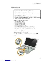
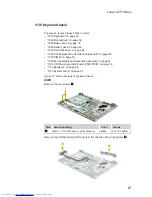
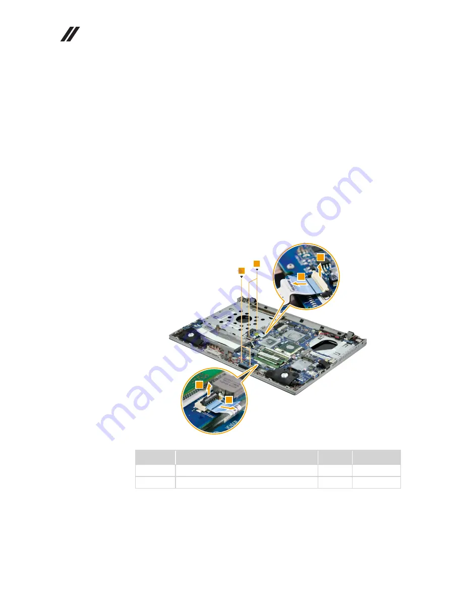
1100 ODD board and LED board (Z500/P500)
For access, remove these FRUs in order:
•
“1010 Keyboard” on page 33
•
“1020 Optical drive” on page 36
•
“1030 Base cover” on page 39
•
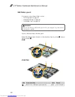
“1040 Battery pack” on page 44
•
“1050 Hard disk drive” on page 46
•
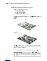
“1060 PCI Express Mini Card for wireless LAN” on page 48
•
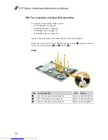
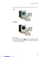
“1080 Fan assembly and Heat Sink assembly” on page 52
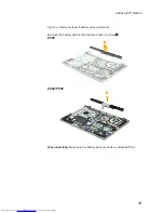
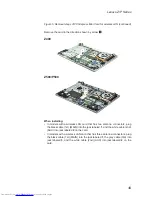
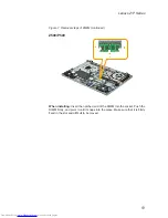
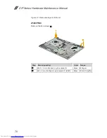
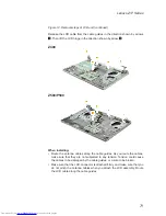
Figure 10. Removal steps of ODD board and LED board
Detach the two FPC connectors in the direction shown by arrows
1
2
.
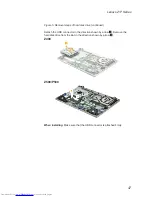
Remove a total of four screws (two
3
and two
4
).
3
4
1
2
1
2
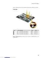
Step
Screw (quantity)
Color
Torque
3
M2 × 2.5, flat-head, nylok-coated (2)
Black
3.62 kg-cm
4
M2 × 3, flat-head, nylok-coated (2)
Black
8.03 kg-cm
Содержание Z series
Страница 1: ...Lenovo Z P Series Hardware Maintenance Manual ...
Страница 78: ...74 Z P Series Hardware Maintenance Manual Figure 15 Removal steps of LCD front bezel Z500 P500 1 1 1 1 ...
Страница 90: ...86 Z P Series Hardware Maintenance Manual Z500 P500 3 3 1 2 4 5 6 7 8 9 10 11 ...
Страница 93: ...89 Lenovo Z P Series Overall Z400 2 3 4 6 13 c 16 18 d a b 8 1 5 e 7 9 10 12 14 19 f 17 ...
Страница 94: ...90 Z P Series Hardware Maintenance Manual Z500 P500 1 2 3 4 6 a b 8 11 13 16 15 c 18 d 5 7 9 10 12 14 f e 17 ...
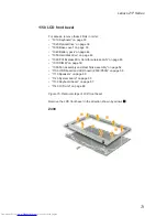
Страница 101: ...97 Lenovo Z P Series LCD FRUs In Lenovo Z400 Z500 P500 there are following types of LCDs 14 in HD TFT 1 2 3 5 4 6 7 ...
Страница 102: ...98 Z P Series Hardware Maintenance Manual 15 6 in HD TFT 1 2 3 5 4 6 7 ...


