background image

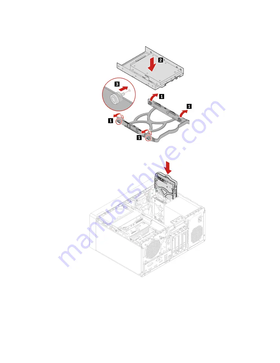
7.  Install the new 2.5-inch storage drive with Type-1 storage drive converter to the 3.5-inch storage drive 

bracket. 

8.  Install Type-1 storage drive converter with the bracket to the 3.5-inch primary storage drive cage. 

9.  Connect the signal cable and the power cable to the new storage drive.

10.  Reinstall all the removed parts. Then, reconnect the power cord and all disconnected cables to the 

computer.

Chapter 8

.

CRU replacement

59

Содержание ThinkStation P340

Страница 1: ...P340 User Guide ...

Страница 2: ...tant safety information on page 109 Safety and Warranty Guide Setup Guide First Edition June 2020 Copyright Lenovo 2020 LIMITED AND RESTRICTED RIGHTS NOTICE If data or software is delivered pursuant to a General Services Administration GSA contract use reproduction or disclosure is subject to restrictions set forth in Contract No GS 35F 05925 ...

Страница 3: ...S guard 23 Use Smart USB Protection 23 Chapter 5 UEFI BIOS 25 What is UEFI BIOS 25 Enter the BIOS menu 25 Navigate in the BIOS interface 25 Change the display language of UEFI BIOS 25 Change the display mode of UEFI BIOS 26 Set the system date and time 26 Change the startup sequence 26 Enable or disable the configuration change detection feature 27 Enable or disable the automatic power on feature ...

Страница 4: ...rage drive in the front access storage enclosure 79 Front fan 87 Rear fan 88 Heat sink and fan assembly 90 Chassis beam 94 Memory module 96 Coin cell battery 98 Power supply assembly 99 E lock 101 Chapter 9 Help and support 103 Self help resources 103 Call Lenovo 104 Before you contact Lenovo 104 Lenovo Customer Support Center 104 Purchase additional services 105 Appendix A System memory speed 107...

Страница 5: ...might not be applicable to your computer Documentation content is subject to change without notice Lenovo makes constant improvements on the documentation of your computer including this User Guide To get the latest documentation go to https pcsupport lenovo com Microsoft makes periodic feature changes to the Windows operating system through Windows Update As a result some information in this docu...

Страница 6: ...iv P340 User Guide ...

Страница 7: ...front access storage enclosure 4 Internal speaker Enable you to experience high quality sound 5 ThinkStation LED This indicator is on when the computer is on 6 Power button Press to turn on the computer To turn off the computer open the Start menu click Power and then select Shut down The indicator in the power button shows the system status of your computer On The computer is on Off The computer ...

Страница 8: ... 1 connector Charge USB C compatible devices with the output voltage and current of 5 V and 3 A Transfer data at USB 3 2 speed up to 5 Gbps Connect to USB C accessories to help expand your computer functionality To purchase USB C accessories go to https www lenovo com accessories 12 USB 3 2 connectors Gen 1 Connect USB compatible devices such as a USB keyboard USB mouse USB storage device or USB p...

Страница 9: ...ectors Send audio and video signals from the computer to another audio or video device such as a high performance monitor 3 Optional connector Depending on the computer model the connector might be a DisplayPort out connector a USB C connector or an HDMI out connector 4 USB 2 0 connectors Connect USB compatible devices such as a USB keyboard USB mouse USB storage device or USB printer 5 USB 3 2 co...

Страница 10: ...se a trackball or other pointing devices that use a Personal System 2 PS 2 keyboard connector 11 Ethernet connector Connect to a local area network LAN When the green indicator is on the computer is connected to a LAN When the yellow indicator blinks data is being transmitted 12 E lock slots Lock the computer cover through an E lock 13 Serial connector Connect an external modem a serial printer or...

Страница 11: ...h secondary storage dirve cage You can install a 2 5 inch storage drive in this cage 3 SD card slot You can install a supported media card into the SD card slot 4 M 2 solid state drive slots One or two M 2 solid state drives are installed in selected models 5 3 5 inch primary storage drive cage You can install a 3 5 inch storage drive or a 2 5 inch storage drive in this cage 6 2 5 inch primary sto...

Страница 12: ...ta rate 4 DDR4 error correction code ECC unbuffered dual inline memory modules UDIMMs or DDR4 non ECC UDIMMs Storage device 2 5 inch hard disk drive 2 5 inch solid state drive 3 5 inch hard disk drive M 2 solid state drive To view the storage drive capacity of your computer right click the Start button to open the Start context menu and then click Disk Management Note The storage drive capacity in...

Страница 13: ...ls Statement on USB transfer rate Depending on many factors such as the processing capability of the host and peripheral devices file attributes and other factors related to system configuration and operating environments the actual transfer rate using the various USB connectors on this device will vary and will be slower than the data rate listed below for each corresponding device USB device Dat...

Страница 14: ...8 P340 User Guide ...

Страница 15: ...s of the Administrator type With an Administrator account you can create additional user accounts or change account types by doing the following 1 Open the Start menu and select Settings Accounts Family other users 2 Follow the on screen instructions Microsoft account You can also log in to the Windows operating system with a Microsoft account To create a Microsoft account go to the Microsoft sign...

Страница 16: ...uter and the Web 8 Task View Display all opened apps and switch among them 9 Windows notification area Display notifications and status of some features 10 Battery status icon Display power status and change battery or power settings When your computer is not connected to ac power the icon changes to 11 Network icon Connect to an available wireless network and display the network status When conne...

Страница 17: ...ndows notification area A list of available wireless networks is displayed 2 Select a network available for connection Provide required information if needed Use Lenovo Vantage The preinstalled Lenovo Vantage is a customized one stop solution to help you maintain your computer with automated updates and fixes configure hardware settings and get personalized support Access Lenovo Vantage Open the S...

Страница 18: ...ot detect the external display right click an empty area of the desktop and then click Display settings Detect Connect to a wireless display To use a wireless display ensure that both your computer and the external display support the Miracast feature Open the Start menu and then click Settings Devices Bluetooth other devices Add Bluetooth or other device In the Add a device window click Wireless ...

Страница 19: ...ge display settings of your preference You can change the settings for both the computer display and the external display For example you can define which one is the main display and which one is the secondary display You also can change the resolution and orientation Note If you set a higher resolution for the computer display than the external display only part of the screen can be displayed on ...

Страница 20: ...14 P340 User Guide ...

Страница 21: ...waken the computer from Sleep mode press any key on your keyboard To reset the power plan to achieve the best balance between performance and power saving 1 Go to Control Panel and view by large icons or small icons 2 Click Power Options and then choose or customize a power plan of your preference Transfer data Quickly share your files using the built in Bluetooth technology among devices with the...

Страница 22: ...Insert a recordable disc into the optical drive that supports recording 2 Do one of the following Open the Start menu and then click Settings Devices AutoPlay Select or turn on Use AutoPlay for all media and devices Open Windows Media Player Double click the ISO file 3 Follow the on screen instructions Use a media card for selected models If your computer has a SD card slot read the following info...

Страница 23: ... cable clip 3 Press the clip 2 into the cable lock slot 3 until it snaps into position Purchase accessories Lenovo has a number of hardware accessories and upgrades to help expand the capabilities of your computer Options include memory modules storage devices network cards power adapters keyboards mice and more To shop at Lenovo go to https www lenovo com accessories Chapter 3 Explore your comput...

Страница 24: ...18 P340 User Guide ...

Страница 25: ...ents or warranties about the function quality or performance of the locking device and security feature You can purchase computer locks from Lenovo Padlock Locking the computer cover through a padlock prevents unauthorized access to the inside of your computer Kensington style cable lock Lock your computer to a desk table or other fixtures through a Kensington style cable lock Copyright Lenovo 202...

Страница 26: ...uthorized access to your computer However you are not prompted to enter any UEFI BIOS password when your computer resumes from sleep mode Power on password When a power on password is set you are prompted to enter a valid password each time the computer is turned on The computer cannot be used until the valid password is entered Supervisor password Setting a supervisor password deters unauthorized...

Страница 27: ...pervisor Password Set Power On Password Set System Management Password or Hard Disk Password and press Enter 4 Follow the on screen instructions to set change or remove a password 5 Press F10 or Fn F10 to save the changes and exit You should record your passwords and store them in a safe place If you forget the passwords see Clear CMOS on page 30 to remove them by yourself You can also contact a L...

Страница 28: ...er The erasing process begins Note During the erasing process the power button and the keyboard are disabled 6 After the erasing process is completed a message is displayed prompting you to reset the system Select Continue Note Depending on the storage drive capacity the erasing process will take half an hour to three hours 7 After the resetting process is completed one of the following will happe...

Страница 29: ...art USB Protection function to one of the following modes Disabled default setting You can use the USB storage devices without limitation Read Only You cannot copy data from the computer to the USB storage devices However you can access or modify data on the USB storage devices No Access You cannot access the USB storage devices from the computer To configure the Smart USB Protection function 1 Re...

Страница 30: ...24 P340 User Guide ...

Страница 31: ... system configurations that are protected by passwords Navigate in the BIOS interface Attention The default configurations are already optimized for you in boldface Improper change of the configurations might cause unexpected results Depending on your keyboard you can navigate in the BIOS interface by pressing the following keys or combinations of Fn and the following keys F1 or Fn F1 Display the ...

Страница 32: ... 1 Depending on the type of the storage device do one of the following If the storage device is internal go to step 2 If the storage device is a disc ensure that the computer is on or turn on the computer Then insert the disc into the optical drive If the storage device is an external device other than a disc connect the storage device to the computer 2 Restart the computer When the logo screen is...

Страница 33: ...t up automatically To enable or disable the automatic power on feature 1 Restart the computer When the logo screen is displayed press F1 or Fn F1 2 Select Power Automatic Power On and press Enter 3 Select the feature as desired and press Enter 4 Enable or disable the feature as desired 5 Press F10 or Fn F10 to save the changes and exit Enable or disable the smart power on feature Ensure that the k...

Страница 34: ...he following Press the power button Enable the Wake Up on Alarm feature to make the computer wake up at a set time To meet the off mode requirement of ErP compliance you need to disable the Fast Startup function 1 Go to Control Panel and view by large icons or small icons 2 Click Power Options Choose what the power buttons do Change settings that are currently unavailable 3 Clear the Turn on fast ...

Страница 35: ...he compatibility list for the Windows version For details go to https support lenovo com us en solutions windows support To change the BIOS settings 1 Restart the computer When the logo screen is displayed press F1 or Fn F1 2 From the main interface select Security Secure Boot and press Enter 3 Depending on the operating system to be installed do one of the following To install the Windows 10 64 b...

Страница 36: ... have been removed Then reconnect the power cords for the computer and the monitor to electrical outlets 11 Turn on the computer and the monitor When the logo screen is displayed press F1 or Fn F1 12 To prevent data loss ensure that BIOS settings are restored to an earlier point For BIOS configurations see Chapter 5 UEFI BIOS on page 25 Clear CMOS 1 Remove all media from the drives and turn off al...

Страница 37: ... RAID below RAID 0 striped disk array Consists of at least two SATA storage drives Supported strip size 4 KB 8 KB 16 KB 32 KB 64 KB or 128 KB Better performance without fault tolerance RAID 1 mirrored disk array Consists of two SATA storage drives Improved reading performance and 100 redundancy RAID 5 block level striped disk array with distributed parity Consists of at least three SATA storage dr...

Страница 38: ...e and press Enter to initiate volume creation Delete RAID volumes in UEFI mode Attention All the existing data stored on the selected drives will be erased after you delete RAID volumes To delete RAID volumes 1 Restart the computer When the logo screen is displayed press F1 or Fn F1 2 Select Devices ATA Drive Setup and press Enter 3 Select Intel R Rapid Storage Technology and press Enter 4 Select ...

Страница 39: ...rectly c All connected devices that require ac power are connected to properly grounded and working electrical outlets d All connected devices are enabled in UEFI BIOS 2 Use an antivirus program if any to see if the computer has been infected by a virus If the program detects a virus remove the virus 3 See Chapter 7 Troubleshooting diagnostics and recovery on page 33 to resolve the problem you are...

Страница 40: ...t up from the correct storage drive or fails to start up Ensure that all storage drive signal cables and power cables are connected correctly Ensure that the storage drive the computer starts up from is listed as the first startup device in UEFI BIOS In rare cases the storage drive with the operating system might get corrupted or damaged In such cases you might need to replace the storage drive If...

Страница 41: ...ts the audio function built into the system board is disabled Therefore you must use the audio connectors on the audio adapter Ensure that the program you are running is designed for use in the Microsoft Windows operating system If the program is designed to run in DOS the program does not use the Windows sound feature The program must be configured to use SoundBlaster Pro or SoundBlaster emulatio...

Страница 42: ... wrong duplex mode might degrade performance cause data loss or result in lost connections When a Gigabit Ethernet model computer is used at a speed of 1000 Mbps the Ethernet LAN connection fails or errors occur Connect the network cable to the Ethernet connector using Category 5 wiring and a 100 BASE T hub switch not 100 BASE X The Wake On LAN WOL feature does not work Enable the Wake On LAN feat...

Страница 43: ... then click Enable device 4 Expand Network adapters to display all network devices Right click each Bluetooth device and then click Enable device Turn on the Bluetooth radio 1 Open the Start menu 2 Click Settings Devices Bluetooth other devices 3 Turn on the Bluetooth switch to enable the Bluetooth feature Update or reinstall the Bluetooth driver Sound does not come from the Bluetooth headset or h...

Страница 44: ...e 1 Open the Start menu 2 Click Windows System File Explorer This PC 3 Right click your C drive and then click Properties 4 Check the amount of free space and then click Disk Cleanup 5 A list of unnecessary file categories is displayed Select the category you want to delete and then click OK Disable some Windows features or remove some unnecessary programs 1 Go to Control Panel and view by large i...

Страница 45: ...aged Try inserting another disc that you know works If you have multiple CD or DVD drives installed or a combination of CD and DVD drives try inserting the disc into the other drive In some cases only one of the drives is connected to the audio subsystem A bootable recovery medium such as the Product Recovery CD cannot be used to start your computer Ensure that the CD or DVD drive is set as the to...

Страница 46: ...cord connect the power cord to a grounded electrical outlet Turn on the serial device and keep the device online Install any programs supplied with the serial device Refer to the documentation that comes with the serial device for more information If you added one serial connector adapter ensure that the adapter is installed correctly USB device problems Problem Solution A USB device cannot be acc...

Страница 47: ... you read and follow the on screen recovery instructions The data on your computer might be deleted during the recovery process To avoid data loss make a backup copy of all the data that you want to keep Restore system files and settings to an earlier point 1 Go to Control Panel and view by large icons or small icons 2 Click Recovery Open System Restore Then follow the on screen instructions Resto...

Страница 48: ...t phone numbers for your country or region go to https pcsupport lenovo com supportphonelist Create a recovery USB drive Attention The creation process deletes anything stored on the USB drive To avoid data loss make a backup copy of all the data that you want to keep 1 Ensure that your computer is connected to ac power 2 Prepare a USB drive with capacity of at least 16 GB The actual USB capacity ...

Страница 49: ...able update packages If the latest UEFI BIOS update package is available follow the on screen instructions to download and install the package From the Lenovo Support Web site Go to https pcsupport lenovo com and select the entry for your computer Then follow the on screen instructions to download and install necessary drivers and software From Windows Update Note The device drivers provided by Wi...

Страница 50: ...44 P340 User Guide ...

Страница 51: ...me upon request You might be required to return the defective part that is replaced by the CRU When return is required 1 return instructions a prepaid shipping label and a container will be included with the replacement CRU and 2 you might be charged for the replacement CRU if Lenovo does not receive the defective CRU within thirty 30 days of your receipt of the replacement CRU For full details se...

Страница 52: ...dix B Important safety information on page 109 and print the following instructions Before you open the computer cover turn off the computer and wait several minutes until the computer is cool Replacement procedure 1 Remove any media from the drives and turn off all connected devices and the computer 2 Disconnect all power cords from electrical outlets and disconnect all cables from the computer 3...

Страница 53: ... removed parts Then reconnect the power cord and all disconnected cables to the computer Note If a locking device is available use it to lock the computer Optical drive Prerequisite Before you start read Appendix B Important safety information on page 109 and print the following instructions Chapter 8 CRU replacement 47 ...

Страница 54: ... procedure 1 Remove the computer cover See Computer cover on page 46 2 Disconnect the signal and power cable from the optical drive 3 Remove the optical drive 4 Remove the optical drive bracket 48 P340 User Guide ...

Страница 55: ...5 Remove the optical drive bezel 6 Instal the optical drive bezel 7 Install the optical drive bracket Chapter 8 CRU replacement 49 ...

Страница 56: ... front bezel remove the plastic shield as shown 9 Install the new optical drive 10 Connect the signal and power cable to the new optical drive 11 Reinstall all the removed parts Then reconnect the power cord and all disconnected cables to the computer 50 P340 User Guide ...

Страница 57: ...rtant safety information on page 109 and print the following instructions Replacement procedure 1 Remove the computer cover See Computer cover on page 46 2 Remove the optical drive See Optical drive on page 47 3 Remove the front bezel Chapter 8 CRU replacement 51 ...

Страница 58: ...air The internal storage drive is not designed for frequent changes or replacement Before replacing the internal storage drive make a backup copy of all the data that you want to keep Do not touch the contact edge of the internal storage drive Otherwise the internal storage drive might get damaged Do not apply pressure to the internal storage drive Do not make the internal storage drive subject to...

Страница 59: ...e upward to release it from the 3 5 inch primary storage drive cage 4 Remove the 2 5 inch primary storage drive with the bracket from the cage 5 Flex the sides of the bracket to remove the storage drive from the bracket Chapter 8 CRU replacement 53 ...

Страница 60: ...bracket 7 Install the storage drive with the bracket to the cage 8 Install the 2 5 inch primary storage drive cage to the 3 5 inch primary storage drive cage 9 Connect the signal cable and the power cable to the new storage drive 54 P340 User Guide ...

Страница 61: ...over See Computer cover on page 46 2 Disconnect the signal cable and the power cable from the 3 5 inch primary storage drive 3 Pull the handle of the 3 5 inch storage drive bracket to remove the storage drive with the bracket from the 3 5 inch primary storage drive cage 4 Flex the sides of the bracket to remove the storage drive from the bracket Chapter 8 CRU replacement 55 ...

Страница 62: ...er cable to the new storage drive 8 Reinstall all the removed parts Then reconnect the power cord and all disconnected cables to the computer 2 5 inch primary storage drive Type 1 storage drive converter and bracket 1 Remove the computer cover See Computer cover on page 46 2 Disconnect the signal cable and the power cable from the 2 5 inch primary storage drive 56 P340 User Guide ...

Страница 63: ...y storage drive converter hereinafter referred to as Type 1 storage drive converter with the bracket from the 3 5 inch primary storage drive cage 4 Flex sides of the bracket to remove the Type 1 storage drive converter from the bracket Chapter 8 CRU replacement 57 ...

Страница 64: ...rage drive Then lift the storage drive out of the Type 1 storage drive converter 6 Install a new 2 5 inch storage drive to Type 1 storage drive converter Then install the four screws to secure the storage drive to Type 1 storage drive converter 58 P340 User Guide ...

Страница 65: ...et 8 Install Type 1 storage drive converter with the bracket to the 3 5 inch primary storage drive cage 9 Connect the signal cable and the power cable to the new storage drive 10 Reinstall all the removed parts Then reconnect the power cord and all disconnected cables to the computer Chapter 8 CRU replacement 59 ...

Страница 66: ...ata that you want to keep Do not touch the contact edge of the internal storage drive Otherwise the internal storage drive might get damaged Do not apply pressure to the internal storage drive Do not make the internal storage drive subject to physical shocks or vibration Put the internal storage drive on a soft material such as cloth to absorb physical shocks Replacement procedure 1 Remove the com...

Страница 67: ...emoved parts Then reconnect the power cord and all disconnected cables to the computer PCI Express card Prerequisite Before you start read Appendix B Important safety information on page 109 and print the following instructions Replacement procedure 1 Remove the computer cover See Computer cover on page 46 Chapter 8 CRU replacement 61 ...

Страница 68: ...4 Reinstall all the removed parts Then reconnect the power cord and all disconnected cables to the computer Graphics card Prerequisite Before you start read Appendix B Important safety information on page 109 and print the following instructions 62 P340 User Guide ...

Страница 69: ...slot and install the other in the PCI Express x4 card slot Graphics card secured with a bracket 1 Remove the computer cover See Computer cover on page 46 2 Remove the optical drive See Optical drive on page 47 3 Remove the front bezel See Front bezel on page 51 4 Disconnect the power cable if any from the graphics card 5 Remove the bracket that secures the graphics card 6 Remove the graphics card ...

Страница 70: ...any to the graphics card 10 Reinstall all the removed parts Then reconnect the power cord and all disconnected cables to the computer Graphics card secured with a plastic holder 1 Remove the computer cover See Computer cover on page 46 2 Disconnect the power cable if any from the graphics card 64 P340 User Guide ...

Страница 71: ...3 Remove the plastic holder that secures the graphics card 4 Remove the graphics card Chapter 8 CRU replacement 65 ...

Страница 72: ... if any to the graphics card 8 Reinstall all the removed parts Then reconnect the power cord and all disconnected cables to the computer M 2 solid state drive and heat sink Prerequisite Before you start read Appendix B Important safety information on page 109 and print the following instructions 66 P340 User Guide ...

Страница 73: ... the internal storage drive might get damaged Do not apply pressure to the internal storage drive Do not make the internal storage drive subject to physical shocks or vibration Put the internal storage drive on a soft material such as cloth to absorb physical shocks M 2 solid state drive and heat sink on the system board 1 Remove the computer cover See Computer cover on page 46 2 Remove the 2 5 in...

Страница 74: ...c Install the M 2 solid state drive d Insert the stopper For computers with the heat sink for the M 2 solid state drive a Pull out the stopper b Remove the heat sink with the bracket 68 P340 User Guide ...

Страница 75: ... drive e Remove the film that covers the thermal pad on the bracket if any Then install the M 2 solid state drive f Remove the film that covers the thermal pad at the bottom of the heat sink if any Then install the heat sink Chapter 8 CRU replacement 69 ...

Страница 76: ... drive PCIe adapter 1 Remove the computer cover See Computer cover on page 46 2 Locate and remove the M 2 solid state drive PCIe adapter from the PCIe card slot See PCI Express card on page 61 3 The heat sink is secured by two mounting studs Pinch the clips of the studs inward and push the studs upward to release the heat sink Then lift the heat sink off the M 2 solid state drive PCIe adapter 70 P...

Страница 77: ...state drive out of the M 2 slot 5 Ensure that a thermal pad is placed in position on the M 2 solid state drive PCIe adapter 6 Pull outward the handle of the retention latch in the M 2 solid state drive adapter 7 Insert the new M 2 solid state drive into the M 2 slot Then insert the plug of the retention latch into the hole to secure the new drive Chapter 8 CRU replacement 71 ...

Страница 78: ... card on page 61 10 Reinstall all the removed parts Then reconnect the power cord and all disconnected cables to the computer M 2 solid state drive bracket Prerequisite Before you start read Appendix B Important safety information on page 109 and print the following instructions Replacement procedure 1 Remove the computer cover See Computer cover on page 46 2 Remove the 2 5 inch primary storage dr...

Страница 79: ...re you start read Appendix B Important safety information on page 109 and print the following instructions Replacement procedure 1 Remove the computer cover See Computer cover on page 46 2 Remove the optical drive See Optical drive on page 47 3 Remove the front bezel See Front bezel on page 51 4 Disconnect the signal cable and power cable from the secondary storage drives under the optical drive c...

Страница 80: ...assis 6 Remove the screw that secures the 3 5 inch secondary storage drive cage to the optical drive cage Then remove the optical drive cage from the 3 5 inch secondary storage drive cage 7 Install the optical drive cage to the 3 5 inch secondary storage drive cage 74 P340 User Guide ...

Страница 81: ...epair The internal storage drive is not designed for frequent changes or replacement Before replacing the internal storage drive make a backup copy of all the data that you want to keep Do not touch the contact edge of the internal storage drive Otherwise the internal storage drive might get damaged Do not apply pressure to the internal storage drive Do not make the internal storage drive subject ...

Страница 82: ...orage drive cage from the 3 5 inch secondary storage drive cage 6 Remove the 2 5 inch secondary storage drive with the bracket from the cage 7 Flex the sides of the bracket to remove the storage drive from the bracket 76 P340 User Guide ...

Страница 83: ... inch secondary storage drive with the bracket to the cage 10 Install the 2 5 inch secondary storage drive cage to the 3 5 inch secondary storage drive cage 11 Reinstall all the removed parts Then reconnect the power cord and all disconnected cables to the computer Chapter 8 CRU replacement 77 ...

Страница 84: ...drive See Optical drive on page 47 4 Remove the optical drive cage See Optical drive cage on page 73 5 Remove the 2 5 inch secondary storage drive cage See 2 5 inch secondary storage drive bracket and cage on page 75 6 Remove the 3 5 inch secondary storage drive with the plastic bracket from the cage 7 Remove the 3 5 inch secondary storage drive from the plastic bracket 78 P340 User Guide ...

Страница 85: ...u start read Appendix B Important safety information on page 109 and print the following instructions Attention The internal storage drive is sensitive Inappropriate handling might cause damage and permanent loss of data When handling the internal storage drive observe the following guidelines Replace the internal storage drive only for upgrade or repair The internal storage drive is not designed ...

Страница 86: ...ly when the following requirements are met The eSATA mode of the SATA 4 connector is enabled in BIOS by doing the following 1 Restart the computer When the logo screen is displayed press F1 or Fn F1 2 Select Devices ATA Drive Setup SATA Drive 4 Hot Plug Support and press Enter 3 Select Enabled and press Enter 4 Press F10 or Fn F10 to save the changes and exit The SATA cable of the front access sto...

Страница 87: ...th the provided key as shown Press the lower end to open the enclosure cover 3 Pull the handle of the bracket to remove the 3 5 inch storage drive with the bracket from the front access storage enclosure Chapter 8 CRU replacement 81 ...

Страница 88: ...ive from the plastic bracket 5 Install a new 3 5 inch storage drive to the plastic bracket 6 Slide the plastic bracket with 3 5 inch storage drive into the front access storage enclosure until it snaps into position 82 P340 User Guide ...

Страница 89: ...storage drive installed in the 3 5 inch front access storage enclosure 1 Before removing an old 2 5 inch storage drive safely eject the old storage drive from the operating system first For more information see the Windows help system 2 Unlock the enclosure cover with the provided key as shown Press the lower end to open the enclosure cover Chapter 8 CRU replacement 83 ...

Страница 90: ...m the front access storage enclosure 4 Flex the sides of the bracket to remove the Type 2 storage drive converter from bracket 5 Pivot the tab of the metal adapter upward Then push the adapter as shown until the four tabs on the adapter slide into the notches Pivot the adapter as shown to remove it with the storage drive from the converter 84 P340 User Guide ...

Страница 91: ...e storage drive Then remove the storage drive from the adapter 7 Note the orientation of the connector on the new storage drive Then flex both sides of the adapter and align the four pins with the corresponding holes in the storage drive Chapter 8 CRU replacement 85 ...

Страница 92: ...de the storage drive as shown until the tab snaps into position The adapter with the storage drive is installed into the converter 9 Flex both sides of the plastic bracket and align pins on the plastic bracket with the corresponding holes in the plastic frame of the converter 86 P340 User Guide ...

Страница 93: ...connected cables to the computer Front fan Prerequisite Before you start read Appendix B Important safety information on page 109 and print the following instructions Replacement procedure 1 Remove the computer cover See Computer cover on page 46 2 Remove the optical drive See Optical drive on page 47 3 Remove the front bezel See Front bezel on page 51 4 Disconnect the front fan cable from the fro...

Страница 94: ...the rubber mounts through the holes Pull the tips of the rubber mounts until the front fan is secured in place 7 Connect the front fan cable to the front fan connector on the system board 8 Reinstall all the removed parts Then reconnect the power cord and all disconnected cables to the computer Rear fan Prerequisite Before you start read Appendix B Important safety information on page 109 and prin...

Страница 95: ...ntly pull the rear fan out of the chassis 4 Align the new rubber mounts of the new rear fan with the corresponding holes in the chassis Push the rubber mounts through the holes Pull the tips of the rubber mounts until the rear fan is secured in place 5 Connect the rear fan cable to the rear fan connector on the system board 6 Reinstall all the removed parts Then reconnect the power cord and all di...

Страница 96: ...n the system board 6 Depending on the computer models the heat sink and fan assembly might vary To replace the heat sink and fan assembly Type 1 a Follow the following sequence to loosen the four screws that secure the heat sink and fan assembly to the system board Then lift the heat sink and fan assembly off the system board Partially loosen screw 1a fully loosen screw 1b and then fully loosen sc...

Страница 97: ...assembly Do not over tighten the screws Partially tighten screw 2a fully tighten screw 2b and then fully tighten screw 2a Partially tighten screw 2c fully tighten screw 2d and then fully tighten screw 2c Notes Apply appropriate amount of thermal grease to the new heat sink and fan assembly Ensure that the heat sink and fan assembly cable is toward the microprocessor fan connector on the system boa...

Страница 98: ...en screw 2c fully loosen screw 2d and then fully loosen screw 2c Notes Carefully loosen the four screws to avoid any possible damage to the system board The four screws cannot be removed from the heat sink and fan assembly You might have to gently twist the heat sink and fan assembly to free it from the microprocessor Do not touch the thermal grease while handling the heat sink and fan assembly In...

Страница 99: ...the four screws to secure the new heat sink and fan assembly to the chassis Partially tighten screw 2a fully tighten screw 2b and then fully tighten screw 2a Partially tighten screw 2c fully tighten screw 2d and then fully tighten screw 2c Notes Apply appropriate amount of thermal grease to the new heat sink and fan assembly In case you need to install the chassis beam as well ensure that it has b...

Страница 100: ...ation on page 109 and print the following instructions Replacement procedure 1 Remove the computer cover See Computer cover on page 46 2 Remove the optical drive See Optical drive on page 47 3 Remove the front bezel See Front bezel on page 51 4 Remove the plastic holder from the chassis beam See Graphics card on page 62 5 Remove the optical drive cage See Optical drive cage on page 73 6 Remove the...

Страница 101: ...7 Pull the plastic latch toward the rear end of the chassis and then push the chassis beam toward the top of the chassis 8 Remove the chassis beam from the chassis Chapter 8 CRU replacement 95 ...

Страница 102: ...all disconnected cables to the computer Memory module Prerequisite Before you start read Appendix B Important safety information on page 109 and print the following instructions Ensure that you follow the installation order for memory modules shown in the following illustration 96 P340 User Guide ...

Страница 103: ...Computer cover on page 46 2 Remove the optical drive See Optical drive on page 47 3 Remove the front bezel See Front bezel on page 51 4 Remove the optical drive cage See Optical drive cage on page 73 5 Remove the memory module Chapter 8 CRU replacement 97 ...

Страница 104: ...time and settings for built in features such as parallel connector assignments configurations A coin cell battery keeps this information active when you turn off the computer The coin cell battery normally requires no charging or maintenance throughout its life however no coin cell battery lasts forever If the coin cell battery fails the date and time information is lost An error message is displa...

Страница 105: ...nd time in the UEFI BIOS menu To dispose of the coin cell battery refer to the Lithium coin cell battery notice in the Safety and Warranty Guide Power supply assembly Prerequisite Before you start read Appendix B Important safety information on page 109 and print the following instructions Before you open the computer cover turn off the computer and wait several minutes until the computer is cool ...

Страница 106: ...that has this label attached There are no serviceable parts inside these components If you suspect a problem with one of these parts contact a service technician Replacement procedure 1 Remove the computer cover See Computer cover on page 46 2 Remove the optical drive See Optical drive on page 47 3 Remove the front bezel See Front bezel on page 51 4 Remove the primary storage drive See Primary sto...

Страница 107: ... the power cord and all disconnected cables to the computer E lock Prerequisite Before you start read Appendix B Important safety information on page 109 and print the following instructions Replacement procedure 1 Remove the computer cover See Computer cover on page 46 2 Disconnect the E lock cable from the system board Chapter 8 CRU replacement 101 ...

Страница 108: ...e the E lock 4 Install the E lock 5 Connect the E lock cable to the system board 6 Reinstall all the removed parts Then reconnect the power cord and all disconnected cables to the computer 102 P340 User Guide ...

Страница 109: ...roduct documentation Safety and Warranty Guide Setup Guide This User Guide Regulatory Notice Go to https pcsupport lenovo com Then follow the on screen instructions to filter out the documentation you want Lenovo Support Web site with the latest support information of the following Drivers and software Diagnostic solutions Product and service warranty Product and parts details Knowledge base and f...

Страница 110: ...ystem are you using Which version Which software applications were running at the time of the problem Can the problem be reproduced If so how 2 Record the system information Product name Machine type and serial number The following illustration shows where to find the machine type and serial number of your computer Lenovo Customer Support Center During the warranty period you can call Lenovo Custo...

Страница 111: ... Lenovo or your reseller if authorized by Lenovo will make selected Engineering Changes ECs that apply to your hardware available Services not covered Replacement or use of parts not manufactured for or by Lenovo or nonwarranted parts Identification of software problem sources Configuration of UEFI BIOS as part of an installation or upgrade Changes modifications or upgrades to device drivers Insta...

Страница 112: ...106 P340 User Guide ...

Страница 113: ...ng on the microprocessor model For example your computer comes with 2933 MT s memory modules but the microprocessor only supports up to 2666 MT s memory modules Then the system memory speed will be no faster than 2666 MT s The microprocessor models supported in your computer might vary For a list of supported microprocessor models contact the Lenovo Customer Support Center The ECC memory modules a...

Страница 114: ...108 P340 User Guide ...

Страница 115: ...n when the computer is unplugged so the battery safety information applies to all computer products Conditions that require immediate action Products can become damaged due to misuse or neglect Some product damage is serious enough that the product should not be used again until it has been inspected and if necessary repaired by an authorized servicer As with any electronic device pay close attent...

Страница 116: ...laceable Units or CRUs Lenovo provides documentation with instructions when it is appropriate for customers to install options or replace CRUs You must closely follow all instructions when installing or replacing parts The Off state of a power indicator does not necessarily mean that voltage levels inside a product are zero Before you remove the covers from a product equipped with a power cord alw...

Страница 117: ...als and or the connector terminals on a power adapter which can eventually result in overheating Ensure that all power cord connectors are securely and completely plugged into receptacles Do not use any power adapter that shows corrosion at the ac input pins or shows signs of overheating such as deformed plastic at the ac input pins or anywhere on the power adapter Do not use any power cords where...

Страница 118: ...s intended to be operated in Denmark Use a cord set with a grounding type attachment plug The cord set should have the appropriate safety approvals for the country in which the equipment will be installed For units intended to be operated in Norway Sweden Finland Use a cord set with a two prong attachment plug The cord set should have the appropriate safety approvals for the country in which the e...

Страница 119: ...onsult an electrician for more information if you have questions about power loads and branch circuit ratings Be sure that the power outlet you are using is properly wired easily accessible and located close to the equipment Do not fully extend power cords in a way that will stress the cords Be sure that the power outlet provides the correct voltage and current for the product you are installing C...

Страница 120: ...e any part of the body seek medical care immediately Do not Throw or immerse into water Heat to more than 100 C 212 F Repair or disassemble Leave in an extremely low air pressure environment Leave in an extremely high temperature environment Crush puncture cut or incinerate Dispose of the battery as required by local ordinances or regulations The following statement applies to users in the state o...

Страница 121: ...er Keep the cover closed whenever the computer is plugged in Regularly inspect the outside of the computer for dust accumulation Remove dust from vents and any perforations in the bezel More frequent cleanings might be required for computers in dusty or high traffic areas Do not restrict or block any ventilation openings Do not store or operate your computer inside furniture as this might increase...

Страница 122: ...cables have been connected to the computer DANGER During electrical storms do not perform any replacement and do not connect the telephone cable to or disconnect it from the telephone outlet on the wall Laser safety information CAUTION When laser products such as CD ROMs DVD drives fiber optic devices or transmitters are installed note the following Do not remove the covers Removing the covers of ...

Страница 123: ...our computer has both a headphone connector and an audio line out connector always use the headphone connector for earphones headphones or a headset However the headphone connector does not support the microphone of the headset If your computer has both a headset connector and an audio line out connector always use the headset connector for earphones headphones or a headset Excessive sound pressur...

Страница 124: ...DANGER Plastic bags can be dangerous Keep plastic bags away from babies and children to avoid danger of suffocation Glass parts notice CAUTION Some parts of your product may be made of glass This glass could break if the product is dropped on a hard surface or receives a substantial impact If glass breaks do not touch or attempt to remove it Stop using your product until the glass is replaced by t...

Страница 125: ...tips on how to minimize visual fatigue please go to https www lenovo com us en safecomp to visit Minimizing Visual Fatigue Tip over hazard prevention notice The computer may cause harm to children if it is not located in an appropriate place Follow the tips below to protect children from harm caused by the computer tipping over Place the computers or monitors on sturdy furniture with a low base or...

Страница 126: ... is not possible place the static protective packaging on a smooth level surface and place the part on it Do not place the part on the computer cover or other metal surface Operating environment Maximum altitude without pressurization Operating From 15 2 m 50 ft to 3048 m 10 000 ft Storage From 15 2 m 50 ft to 10 668 m 35 000 ft Temperature Operating From 10 C 50 F to 35 C 95 F Storage without pac...

Страница 127: ...perating system even if Windows fails to start up Get the most up to date operating system update patches software programs and device drivers Maintenance tips about moving the computer Before moving the computer take the following precautions 1 Back up your data on the storage drive 2 Remove any media from the drives and turn off all connected devices and the computer Then disconnect all power co...

Страница 128: ...ht can affect the performance of your computer screen Use a dry soft lint free cloth to wipe the screen gently If you see a scratchlike mark on your screen it might be a stain Wipe or dust the stain gently with a soft dry cloth If the stain remains moisten a soft lint free cloth with water or eyeglass cleaner but do not apply liquids directly to your computer screen Ensure that the computer screen...

Страница 129: ...k Turn on or turn off Mouse Keys Left Alt Left Shift PrtScn or PrtSc Turn on or turn off High Contrast For more information go to https windows microsoft com and then search using any of the following keywords keyboard shortcuts key combinations shortcut keys Ease of Access Center Ease of Access Center on the Windows operating system enables you to configure your computers to suit their physical a...

Страница 130: ...e and send e mails To use Speech Recognition 1 Go to Control Panel and view by Category 2 Click Ease of Access Speech Recognition 3 Follow the on screen instructions Screen reader technologies Screen reader technologies are primarily focused on software program interfaces help systems and various online documents For additional information about screen readers see the following Use PDFs with scree...

Страница 131: ...ough a screen reader Each image in the documentation also includes adequate alternative text so that visually impaired users can understand the image when they use a screen reader Ergonomic information Good ergonomic practice is important to get the most from your personal computer and to avoid discomfort Arrange your workplace and the equipment you use to suit your individual needs and the kind o...

Страница 132: ...ep your head and neck in a comfortable and neutral vertical or upright position Chair Use a chair that gives you good back support and seat height adjustment Use chair adjustments to best suit your comfort posture Arm and hand position If available use chair arm rests or an area on your working surface to provide weight support for your arms Keep your forearms wrists and hands in a relaxed and neu...

Страница 133: ...b site or from your computer contact your local Lenovo office or reseller to obtain a printed version of the LLW Access the Ubuntu help system The Ubuntu help system provides information about how to use the Ubuntu operating system To access the help system from Home Screen move your pointer to the Launch bar and then click the Help icon If you cannot find the Help icon from the Launch bar click t...

Страница 134: ...128 P340 User Guide ...

Страница 135: ...odification of the product including the installation of option cards from other manufacturers This product has been tested and found to comply with the limits for Class B equipment according to European Standards harmonized in the Directives in compliance The limits for Class B equipment were derived for typical residential environments to provide reasonable protection against interference with l...

Страница 136: ...n about Lenovo products Recycling and environmental information Lenovo encourages owners of information technology IT equipment to responsibly recycle their equipment when it is no longer needed Lenovo offers a variety of programs and services to assist equipment owners in recycling their IT products For information about recycling Lenovo products go to https www lenovo com us en compliance recycl...

Страница 137: ...posed of by an industrial waste disposal contractor certified by a local government In accordance with the Law for Promotion of Effective Utilization of Resources Lenovo Japan provides through its PC Collecting and Recycling Services for the collecting reuse and recycling of disused computers and monitors For details visit the Lenovo Web site at https www lenovo com us en social_responsibility sus...

Страница 138: ...imed upon end of life per this Directive In accordance with the European Directive 2006 66 EC batteries and accumulators are labeled to indicate that they are to be collected separately and recycled at end of life The label on the battery may also include a chemical symbol for the metal concerned in the battery Pb for lead Hg for mercury and Cd for cadmium Users of batteries and accumulators must ...

Страница 139: ...o com lenovo environment Recycling information for mainland China Battery recycling information for Taiwan Restriction of Hazardous Substances RoHS Directive of countries and regions The latest environmental information about Lenovo products is available at https www lenovo com ecodeclaration European Union RoHS This Lenovo product with included parts cables cords and so on meets the requirements ...

Страница 140: ...India RoHS RoHS compliant as per E Waste Management Rules Mainland China RoHS Taiwan RoHS 134 P340 User Guide ...

Страница 141: ...Connect the equipment into an outlet on a circuit different from that to which the receiver is connected Consult an authorized dealer or service representative for help Lenovo is not responsible for any radio or television interference caused by using other than recommended cables and connectors or by unauthorized changes or modifications to this equipment Unauthorized changes or modifications cou...

Страница 142: ... den Handbüchern beschrieben zu installieren und zu betreiben Des Weiteren dürfen auch nur von der Lenovo empfohlene Kabel angeschlossen werden Lenovo übernimmt keine Verantwortung für die Einhaltung der Schutzanforderungen wenn das Produkt ohne Zustimmung der Lenovo verändert bzw wenn Erweiterungskomponenten von Fremdherstellern ohne Empfehlung der Lenovo gesteckt eingebaut werden Zulassungsbesch...

Страница 143: ...details go to https www lenovo com us en compliance tco Export classification notice This product is subject to the United States Export Administration Regulations EAR and has an Export Classification Control Number ECCN of 5A992 c It can be re exported except to any of the embargoed countries in the EAR E1 country list Lenovo product service information for Taiwan Taiwan precautionary vision stat...

Страница 144: ...TAR mark may be affixed to the product the product packaging or displayed electronically on the E label screen or the power settings interface By using ENERGY STAR compliant products and taking advantage of the power management features of your computer you reduce the consumption of electricity Reduced electrical consumption contributes to potential financial savings a cleaner environment and the ...

Страница 145: ...ht to improve and or modify the products and software programs described in the manuals included with your computer and the content of the manual at any time without additional notice The software interface and function and hardware configuration described in the manuals included with your computer might not match exactly the actual configuration of the computer that you purchase For the configura...

Страница 146: ...his document at any time without notice For the latest information or any questions or comments contact or visit the Lenovo Web site https pcsupport lenovo com Trademarks LENOVO LENOVO logo THINKSTATION and THINKSTATION logo are trademarks of Lenovo Intel Optane and Core are trademarks of Intel Corporation or its subsidiaries in the U S and or other countries Microsoft Windows Direct3D and Cortana...

Страница 147: ......

Страница 148: ......

Отзывы: