


1.
Turn off the computer and disconnect all external devices.
2.
Power-on the computer.
3.
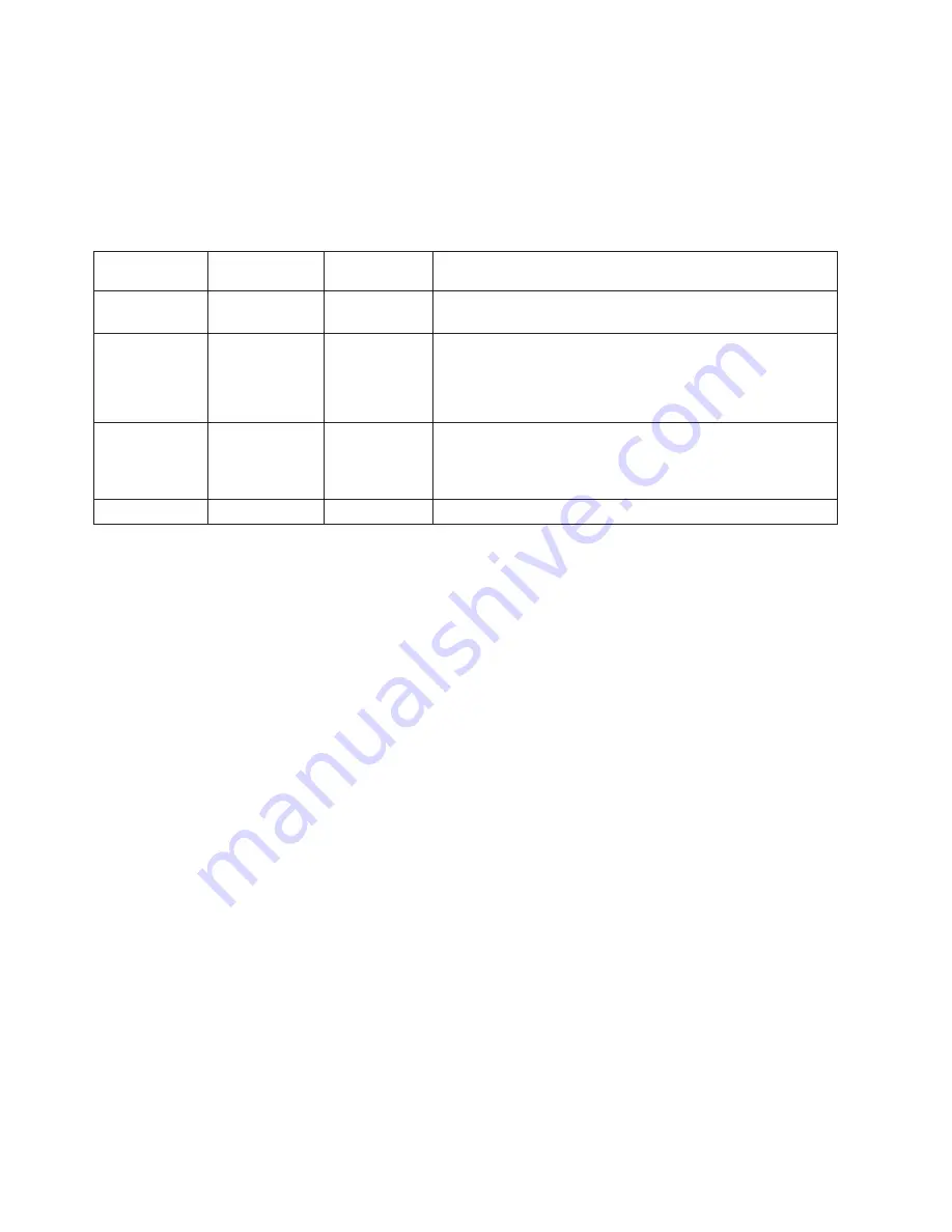
There are three LEDs to help you determine if the power supply and system
board are working correctly. The power button LED is located on the front of
the computer and the two diagnostic LEDs are located on the power supply at
the rear of the computer. After pressing the power button, observe the LEDs
and refer to the following table:
Power LED
Green
diagnostic LED
Yellow
diagnostic LED Action
ON
ON
OFF
This is the normal condition of the LEDs when the power is
OK.
OFF
OFF
OFF
v
Make sure the power cord is attached to a working
electrical outlet.
v
Check the power cord for continuity.
v
If the problem persists, replace the power supply.
OFF (after the
power button
has been
pressed)
ON
OFF
Replace the system board
ON
ON
ON
Replace the power supply
If the Diagnostic LEDs are in the normal condition and the problem persists,
replace the system board and the microprocessor, one at a time, until the
computer works correctly.
60
Hardware Maintenance Manual
Содержание THINKSTATION D10
Страница 1: ......
Страница 2: ......
Страница 3: ...ThinkStation Hardware Maintenance Manual ...
Страница 17: ...Chapter 2 Safety information 11 ...
Страница 18: ...12 Hardware Maintenance Manual ...
Страница 19: ... 18 kg 37 lbs 32 kg 70 5 lbs 55 kg 121 2 lbs 1 2 Chapter 2 Safety information 13 ...
Страница 23: ...Chapter 2 Safety information 17 ...
Страница 24: ...1 2 18 Hardware Maintenance Manual ...
Страница 25: ...Chapter 2 Safety information 19 ...
Страница 26: ...1 2 20 Hardware Maintenance Manual ...
Страница 33: ...Chapter 2 Safety information 27 ...
Страница 34: ...28 Hardware Maintenance Manual ...
Страница 35: ...1 2 Chapter 2 Safety information 29 ...
Страница 39: ...Chapter 2 Safety information 33 ...
Страница 40: ...1 2 34 Hardware Maintenance Manual ...
Страница 44: ...38 Hardware Maintenance Manual ...
Страница 54: ...48 Hardware Maintenance Manual ...
Страница 58: ...52 Hardware Maintenance Manual ...
Страница 64: ...58 Hardware Maintenance Manual ...
Страница 94: ...88 Hardware Maintenance Manual ...
Страница 103: ...Chapter 9 Replacing FRUs types 6423 and 6483 97 ...
Страница 106: ...100 Hardware Maintenance Manual ...
Страница 130: ...124 Hardware Maintenance Manual ...
Страница 140: ...134 Hardware Maintenance Manual ...
Страница 158: ...8 Go to Completing the FRU replacement on page 158 152 Hardware Maintenance Manual ...
Страница 161: ...6 Go to Completing the FRU replacement on page 158 Chapter 10 Replacing FRUs types 6427 and 6493 155 ...
Страница 247: ......
Страница 248: ...Part Number 43C9807 Printed in USA 1P P N 43C9807 ...


