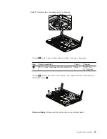
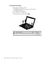


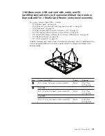
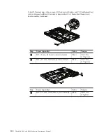

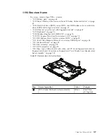


Table
28.
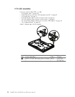
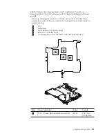
Removal
steps
of
base
cover,
USB
sub
card
with
cable,
and
PC
Card/ExpressCard
slots
(or
ExpressCard/Smart
Card
slots
or
ExpressCard/7-in-1
Media
Card
Reader
slots)
bezel
assembly
(continued)
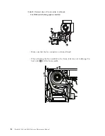
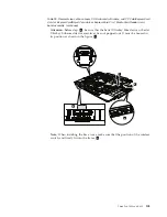
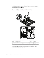
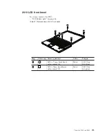
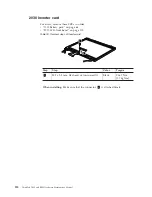
Attention:
Before
step
8
,
be
sure
that
the
Serial
Ultrabay
Slim
device
or
Serial
Ultrabay
Enhanced
device
eject
lever
has
not
popped
out.
It
must
be
housed
in
its
position
as
shown
in
the
figure
a
.
a
b
7
8
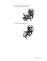
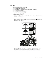
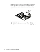
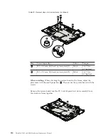
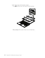
Note:
When
installing
the
base
cover,
make
sure
that
the
position
of
the
wireless
switch,
and
firmly
fit
into
the
frame
b
.
ThinkPad
T400
and
R400
103
Содержание ThinkPad R400
Страница 1: ...ThinkPad T400 and R400 Hardware Maintenance Manual ...
Страница 2: ......
Страница 3: ...ThinkPad T400 and R400 Hardware Maintenance Manual ...
Страница 8: ...vi ThinkPad T400 and R400Hardware Maintenance Manual ...
Страница 24: ...16 ThinkPad T400 and R400Hardware Maintenance Manual ...
Страница 30: ...22 ThinkPad T400 and R400Hardware Maintenance Manual ...
Страница 40: ...32 ThinkPad T400 and R400Hardware Maintenance Manual ...
Страница 301: ......
Страница 302: ...Part Number 43Y6629_03 1P P N 43Y6629_03 ...