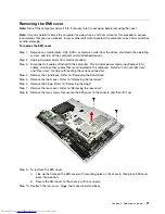


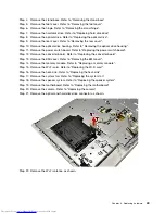
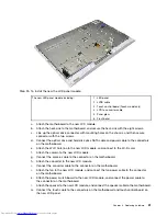


Step 25. To install the new the LCD panel module:
The new LED panel module including:
1. LED panel
2. LVDS cable
3. Touch control board (Touch model only)
4. LCD to converter cable
5. Panel glass
6. Front bezel
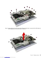
a.
Attach the motherboard to the new LCD module.
b.
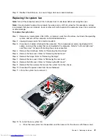
Attach the heat-sink to the motherboard, and secure the heat-sink with the eight screws.
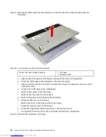
c.
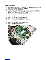
Line up the optical drive connector with mounting holes on the chassis, and then secure
connector with the two screws.
d.
Connect the optical drive and hard disk drive SATA cable and power cable to the connectors
on the motherboard.
e.
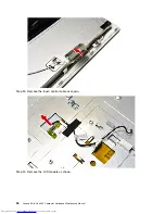
Attach the Wi-Fi Antenna to the new LCD module, and connect to the Wi-Fi card.
f.
Attach the camera to the new LCD module.
g.
Connect the camera cable to the connector on the motherboard.
h.
Attach the converter to the new LCD module.
i.
Connect the converter cable to the connector on the motherboard.
j.
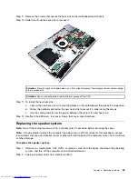
Attach the fan to the new LCD module, and connect the fan power cable to the connector
on the motherboard.
k.
Attach the power switch board to the new LCD module, and connect the power cable to
the connector on the motherboard.
l.
Attach the speaker to the new LCD module, and connect the speaker cable to the motherboard.
m. Connect the touch cable to the connectors on the motherboard and touch control board on
the new LCD panel.
Chapter 8
.
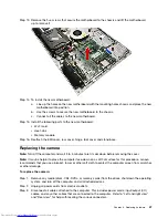
Replacing hardware
51
Содержание Thinkpad 300
Страница 2: ......
Страница 6: ...iv Lenovo All In One 300 Computer Hardware Maintenance Manual ...
Страница 8: ...2 Lenovo All In One 300 Computer Hardware Maintenance Manual ...
Страница 16: ...10 Lenovo All In One 300 Computer Hardware Maintenance Manual ...
Страница 18: ...12 Lenovo All In One 300 Computer Hardware Maintenance Manual ...
Страница 24: ...18 Lenovo All In One 300 Computer Hardware Maintenance Manual ...
Страница 32: ...26 Lenovo All In One 300 Computer Hardware Maintenance Manual ...