


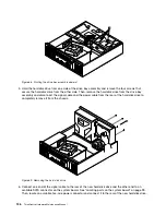


11. Pivot the drive bay assembly upward. Then, connect the new front audio and USB assembly cables to
the front USB connector and the front audio connector on the system board. See “Locating parts on the
system board” on page 99.
12. Properly route the cables of the new front audio and USB assembly, and then secure the cables with
the cable clip on the chassis. See Cable routing (For a clear illustration of the cable routing, some
components are not shown here.).
13. To complete the replacement, go to “Completing the parts replacement” on page 132.
Replacing the front fan assembly
Attention
Do not open your computer or attempt any repair before reading and understanding the “Important safety information”
in the
ThinkCentre Safety and Warranty Guide
that came with your computer. To obtain a copy of the
ThinkCentre
Safety and Warranty Guide
, go to:
http://www.lenovo.com/support
This section provides instructions on how to replace the front fan assembly.
To replace the front fan assembly, do the following:
1. Remove all media from the drives and turn off all attached devices and the computer. Then, disconnect
all power cords from electrical outlets and disconnect all cables that are connected to the computer.
2. Remove the computer cover. See “Removing the computer cover” on page 101.
3. Remove the front bezel. See “Removing and reinstalling the front bezel” on page 102.
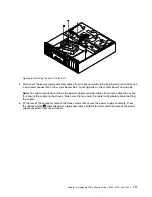
4. Pivot the drive bay assembly upward to gain access to the front fan assembly. See “Accessing the
system board components and drives” on page 104.
5. Remove the hard disk drive for easier access to the front fan assembly. See “Replacing the hard
disk drive” on page 125.
6. Remove the heat sink fan duct. See “Replacing the heat sink and fan assembly” on page 110.
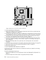
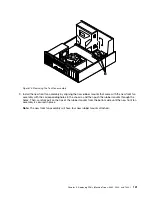
7. Note the cable routing and disconnect the front fan assembly cable from the system fan connector on
the system board. See “Locating parts on the system board” on page 99.
8. The front fan assembly is attached to the chassis by four rubber mounts
1
. Remove the front fan
assembly by cutting the rubber mounts and lifting the front fan assembly out of the chassis.
130
ThinkCentre Hardware Maintenance Manual
Содержание ThinkCentre A70
Страница 1: ...ThinkCentre Hardware Maintenance Manual Machine Types 0864 0889 5023 7099 7844 and 7846 ...
Страница 2: ......
Страница 3: ...ThinkCentre Hardware Maintenance Manual Machine Types 0864 0889 5023 7099 7844 and 7846 ...
Страница 15: ...Chapter 2 Safety information 9 ...
Страница 16: ... 18 kg 37 lbs 32 kg 70 5 lbs 55 kg 121 2 lbs 1 2 PERIGO 10 ThinkCentre Hardware Maintenance Manual ...
Страница 19: ...Chapter 2 Safety information 13 ...
Страница 20: ...1 2 14 ThinkCentre Hardware Maintenance Manual ...
Страница 21: ...Chapter 2 Safety information 15 ...
Страница 27: ...Chapter 2 Safety information 21 ...
Страница 31: ...Chapter 2 Safety information 25 ...
Страница 72: ...66 ThinkCentre Hardware Maintenance Manual ...
Страница 102: ...96 ThinkCentre Hardware Maintenance Manual ...
Страница 264: ...258 ThinkCentre Hardware Maintenance Manual ...
Страница 269: ......
Страница 270: ...Part Number 89Y9149 Printed in USA 1P P N 89Y9149 89Y9149 ...


