


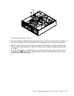


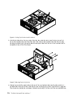


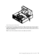


Figure 58. Installing the power supply assembly
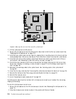
9. Connect the new power supply assembly cables to all drives and to the 24-pin power connector and
4-pin power connector on the system board. See “Locating parts on the system board” on page 99.
10. Make sure that the cables are routed properly. See Cable routing (For a clear illustration of the cable
routing, some components are not shown here.).
11. Position the heat sink fan duct on the top of the heat sink and fan assembly so that the four screw holes
in the heat sink fan duct are aligned with the corresponding holes in the heat sink and fan assembly.
Then, install the four screws to secure the heat sink fan duct in place.
Chapter 9
.
Replacing FRUs (Machine Types: 0889, 5023, and 7844.)
119
Содержание ThinkCentre A70
Страница 1: ...ThinkCentre Hardware Maintenance Manual Machine Types 0864 0889 5023 7099 7844 and 7846 ...
Страница 2: ......
Страница 3: ...ThinkCentre Hardware Maintenance Manual Machine Types 0864 0889 5023 7099 7844 and 7846 ...
Страница 15: ...Chapter 2 Safety information 9 ...
Страница 16: ... 18 kg 37 lbs 32 kg 70 5 lbs 55 kg 121 2 lbs 1 2 PERIGO 10 ThinkCentre Hardware Maintenance Manual ...
Страница 19: ...Chapter 2 Safety information 13 ...
Страница 20: ...1 2 14 ThinkCentre Hardware Maintenance Manual ...
Страница 21: ...Chapter 2 Safety information 15 ...
Страница 27: ...Chapter 2 Safety information 21 ...
Страница 31: ...Chapter 2 Safety information 25 ...
Страница 72: ...66 ThinkCentre Hardware Maintenance Manual ...
Страница 102: ...96 ThinkCentre Hardware Maintenance Manual ...
Страница 264: ...258 ThinkCentre Hardware Maintenance Manual ...
Страница 269: ......
Страница 270: ...Part Number 89Y9149 Printed in USA 1P P N 89Y9149 89Y9149 ...


