


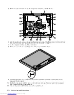


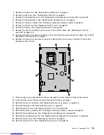
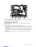


5. Remove the 21 screws that secure the computer main bracket to the front bezel.
6. Note the locations of all cable connections that prevent you from lifting the computer main bracket, and
disconnect all cables. See “System board parts and connectors” on page 71.
7. Lift the computer main bracket off the front bezel.
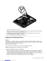
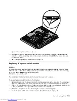
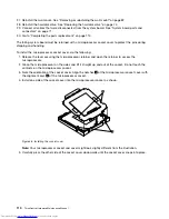
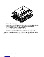
8. Remove the screw that secures the power switch module to the front bezel.
9. Disconnect the power switch module cable from the system board, and then lift the power switch
module off the front bezel.
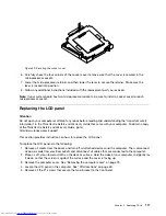
10. Position the new power switch module on the front bezel and align the screw hole in the new power
switch module with that in the front bezel.
11. Connect the power switch module cable to the system board.
106
ThinkCentre Hardware Maintenance Manual
Содержание ThinkCentre 7570
Страница 2: ......
Страница 15: ...Chapter 2 Safety information 9 ...
Страница 16: ... 18 kg 37 lbs 32 kg 70 5 lbs 55 kg 121 2 lbs 1 2 PERIGO 10 ThinkCentre Hardware Maintenance Manual ...
Страница 19: ...Chapter 2 Safety information 13 ...
Страница 20: ...1 2 14 ThinkCentre Hardware Maintenance Manual ...
Страница 21: ...Chapter 2 Safety information 15 ...
Страница 27: ...Chapter 2 Safety information 21 ...
Страница 31: ...Chapter 2 Safety information 25 ...
Страница 38: ...32 ThinkCentre Hardware Maintenance Manual ...
Страница 202: ...196 ThinkCentre Hardware Maintenance Manual ...
Страница 207: ......
Страница 208: ...Part Number 0A22568 Printed in USA 1P P N 0A22568 0A22568 ...


