


System board parts and connectors
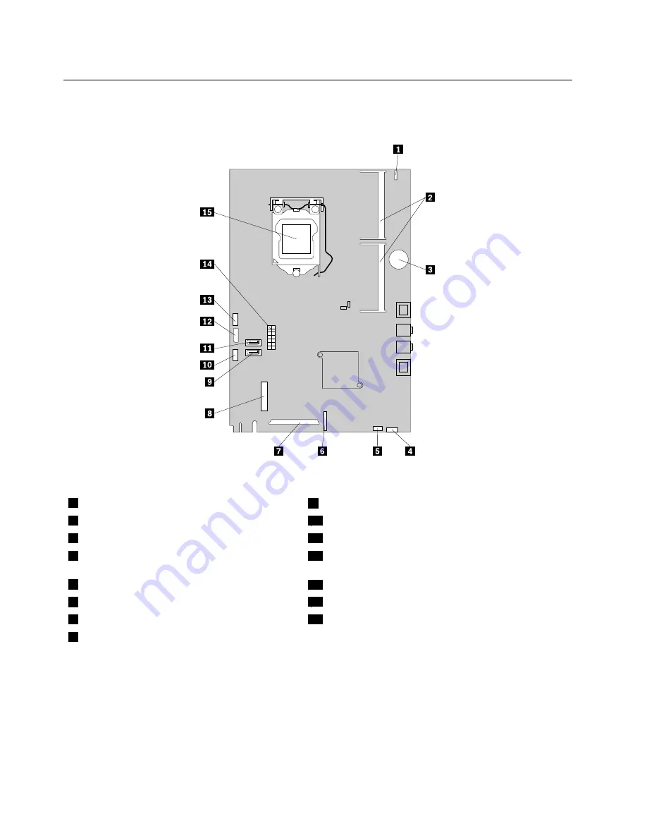
The following illustration shows the locations of the system board parts and connectors.
Figure 4. System board part and connector locations
1
Integrated camera cable connector
9
SATA connector
2
Memory slots (2)
10
Microprocessor fan connector
3
Battery
11
SATA connector
4
Card reader connector
12
Optical drive power connector/Hard disk drive power
connector
5
Internal speaker cable connector
13
Converter board connector
6
Control button connector
14
Power supply connector
7
LCD panel connector
15
Microprocessor
8
WI-FI connector
72
ThinkCentre Hardware Maintenance Manual
Содержание ThinkCentre 3512
Страница 2: ......
Страница 8: ...2 ThinkCentre Hardware Maintenance Manual ...
Страница 15: ...Chapter 2 Safety information 9 ...
Страница 19: ...Chapter 2 Safety information 13 ...
Страница 20: ...1 2 14 ThinkCentre Hardware Maintenance Manual ...
Страница 21: ...1 2 Chapter 2 Safety information 15 ...
Страница 26: ...1 2 20 ThinkCentre Hardware Maintenance Manual ...
Страница 27: ...1 2 Chapter 2 Safety information 21 ...
Страница 30: ...24 ThinkCentre Hardware Maintenance Manual ...
Страница 34: ...28 ThinkCentre Hardware Maintenance Manual ...
Страница 60: ...54 ThinkCentre Hardware Maintenance Manual ...
Страница 70: ...64 ThinkCentre Hardware Maintenance Manual ...
Страница 73: ...6 PS 2 mouse connector optional 13 USB connector USB port 1 7 Serial port Chapter 8 Locations 67 ...
Страница 75: ...Figure 3 Locating major FRUs and CRUs Chapter 8 Locations 69 ...
Страница 85: ...Figure 12 Removing the frame stand Chapter 9 Replacing FRUs 79 ...
Страница 127: ......
Страница 128: ......