


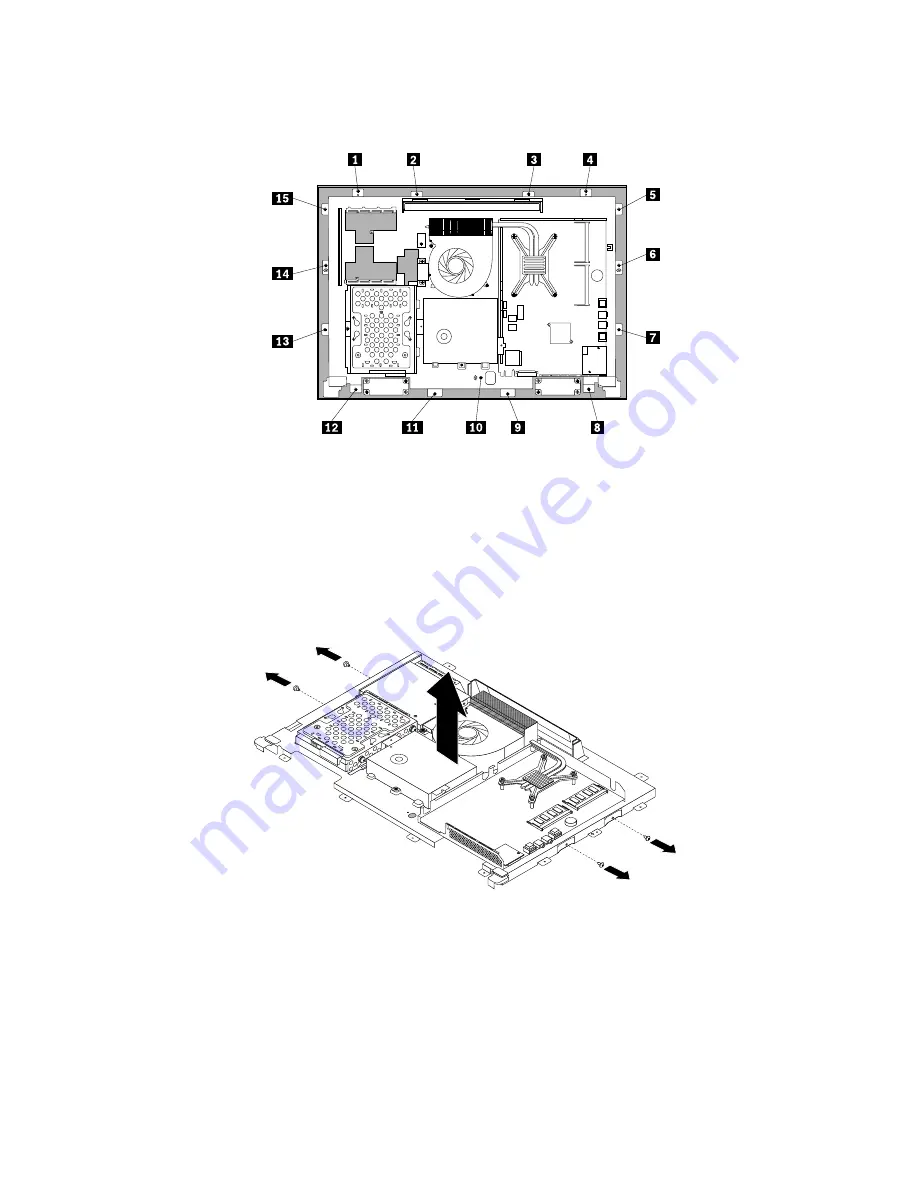
11. Remove all the 15 screws that secure the computer main bracket to the front bezel.
Figure 44. Removing all the 15 screws that secure the computer main bracket to the front bezel
12. Note the locations of all cable connections that prevent you from lifting the computer main bracket, and
disconnect all cables. See “System board parts and connectors” on page 72.
13. Remove the integrated camera. See “Replacing the integrated camera” on page 103.
14. Lift the computer main bracket off the front bezel.
15. Remove the four screws that secure the chassis to the LCD panel, and then lift the chassis out of
the computer to get assess to the LCD panel.
Figure 45. Removing the four screws that secure the LCD panel
16. Place the computer chassis over the new LCD panel so that the four screw holes align with those in the
chassis. Reinstall the four screws to secure the LCD panel to the chassis.
17. Position the computer main bracket over the LCD panel. Make sure the screw holes in the computer
main bracket align with those in the front bezel.
18. Reinstall all the 15 screws that secure the computer main bracket to the front bezel.
108
ThinkCentre Hardware Maintenance Manual
Содержание ThinkCentre 3512
Страница 2: ......
Страница 8: ...2 ThinkCentre Hardware Maintenance Manual ...
Страница 15: ...Chapter 2 Safety information 9 ...
Страница 19: ...Chapter 2 Safety information 13 ...
Страница 20: ...1 2 14 ThinkCentre Hardware Maintenance Manual ...
Страница 21: ...1 2 Chapter 2 Safety information 15 ...
Страница 26: ...1 2 20 ThinkCentre Hardware Maintenance Manual ...
Страница 27: ...1 2 Chapter 2 Safety information 21 ...
Страница 30: ...24 ThinkCentre Hardware Maintenance Manual ...
Страница 34: ...28 ThinkCentre Hardware Maintenance Manual ...
Страница 60: ...54 ThinkCentre Hardware Maintenance Manual ...
Страница 70: ...64 ThinkCentre Hardware Maintenance Manual ...
Страница 73: ...6 PS 2 mouse connector optional 13 USB connector USB port 1 7 Serial port Chapter 8 Locations 67 ...
Страница 75: ...Figure 3 Locating major FRUs and CRUs Chapter 8 Locations 69 ...
Страница 85: ...Figure 12 Removing the frame stand Chapter 9 Replacing FRUs 79 ...
Страница 127: ......
Страница 128: ......