Lenovo THINK STATION 4262 Скачать руководство пользователя страница 67

Chapter 7. Troubleshooting and diagnostic programs

This chapter provides information about some basic troubleshooting and diagnostic programs. If your
computer problem is not described in this chapter, see Chapter 8 “Getting information, help, and service” on
page 65 for additional troubleshooting resources.

This chapter contains the following topics:

“Basic troubleshooting” on page 61

“Diagnostic programs” on page 62

“Cleaning an optical mouse” on page 64

Basic troubleshooting

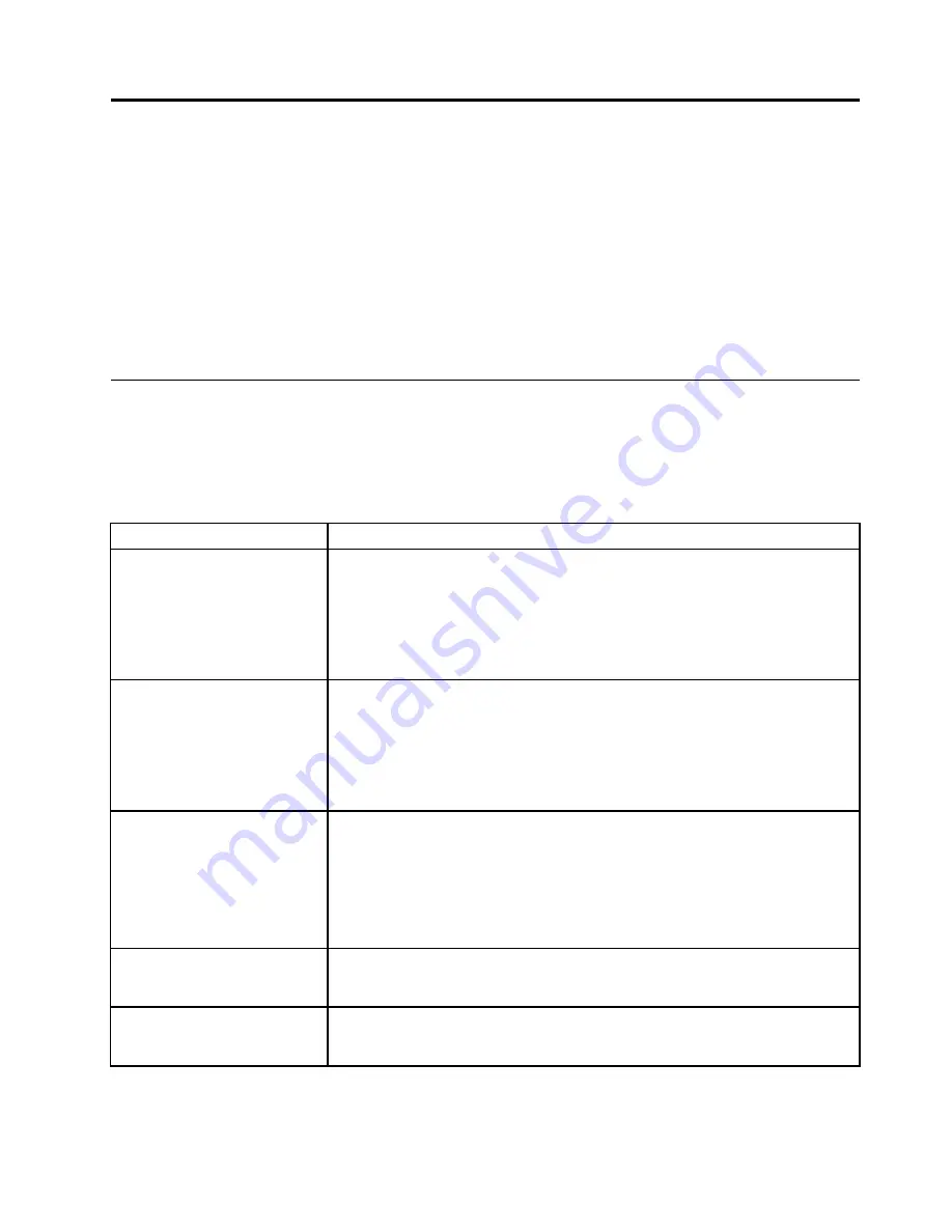
The following table provides some basic information to help you troubleshoot your computer problems.

Note:

If you cannot solve the problem after doing the basic troubleshooting, have the computer serviced.

Refer to the

ThinkStation Safety and Warranty Guide

that came with your computer for the safety and

warranty information and the list of Lenovo Support telephone numbers.

Symptom

Action

The computer does not start
when you press the power
switch.

Verify that:

• The power cord is correctly connected to the rear of the computer and to a

working electrical outlet.

• The power indicator on the front of the computer is on.

• The computer voltage matches the voltage available at the electrical outlet for

your country or region.

The monitor screen is blank.

Verify that:

• The power cord is correctly connected to the rear of the computer and to a

working electrical outlet.

• The computer voltage matches the voltage available at the electrical outlet for

your country or region.

• The brightness and contrast controls are set correctly.

The USB keyboard or mouse
does not work.

Verify that:

• The computer is turned on.

• The keyboard or mouse is correctly connected to one of the USB connectors

on the computer.

• For the keyboard, no keys are stuck.

• The mouse is clean. Refer to “Cleaning an optical mouse” on page 64.

The operating system does not
start.

Verify that you list the device where the operating system resides in the startup
device sequence. Usually, the operating system is on the hard disk drive. For more
information, see “Selecting a startup device” on page 51.

The computer beeps multiple
times before the operating
system starts.

Verify that no keys are stuck.

© Copyright Lenovo 2010, 2011

61

Содержание THINK STATION 4262

Страница 1: ...ThinkStation User Guide Machine Types 4262 4263 4264 4265 4266 4269 4271 and 4272 ...

Страница 2: ...arranty Guide and Appendix B Notices on page 73 Third Edition December 2011 Copyright Lenovo 2010 2011 LIMITED AND RESTRICTED RIGHTS NOTICE If data or software is delivered pursuant a General Services Administration GSA contract use reproduction or disclosure is subject to restrictions set forth in Contract No GS 35F 05925 ...

Страница 3: ...erforming a recovery operation 43 Using the Rescue and Recovery workspace 44 Creating and using a rescue medium 45 Creating a rescue medium 45 Using a rescue medium 45 Installing or reinstalling device drivers 46 Solving recovery problems 46 Chapter 4 Using the Setup Utility program 49 Starting the Setup Utility program 49 Viewing or changing settings 49 Using passwords 49 Password considerations ...

Страница 4: ...S 63 Cleaning an optical mouse 64 Chapter 8 Getting information help and service 65 Information resources 65 Online Books folder 65 Lenovo ThinkVantage Tools 65 Lenovo Welcome 65 Safety and warranty 66 Lenovo Web site http www lenovo com 66 Help and service 66 Using the documentation and diagnostic programs 66 Calling for service 66 Using other services 67 Purchasing additional services 68 Appendi...

Страница 5: ...t you received with this product for the latest safety information Reading and understanding this safety information reduces the risk of personal injury and or damage to your product If you no longer have a copy of the ThinkCentre Safety and Warranty Guide you can obtain a Portable Document Format PDF version from the Lenovo Support Web site at http support lenovo com Copyright Lenovo 2010 2011 ii...

Страница 6: ...iv ThinkStation User Guide ...

Страница 7: ...llowing microprocessors internal cache size varies by model type Intel Xeon Dual Core microprocessor Intel Xeon Quad Core microprocessor Intel Xeon Six Core microprocessor Memory module s Supports up to six or 12 double data rate 3 dual inline memory modules DDR3 DIMMs Each microprocessor supports up to three or six memory modules Note The Intel Xeon microprocessor families compatible with this Th...

Страница 8: ... Alert Standard Format ASF 2 0 Automatic power on startup Preboot Execution Environment PXE System Management SM Basic Input Output System BIOS and SM software Wake on LAN Wake on Ring in the Setup Utility program this feature is called Serial Port Ring Detect for an external modem Windows Management Instrumentation WMI Input Output I O features 9 pin serial port available on some models 10 USB Un...

Страница 9: ... software programs to help you work more easily and securely For more information see Software overview on page 4 Preinstalled operating system Your computer is preinstalled with one of the following operating systems Microsoft Windows 7 Microsoft Windows XP Professional preinstalled through downgrade rights in Windows 7 Professional Operating system s certified or tested for compatibility1 varies...

Страница 10: ...ng system and several preinstalled applications Software provided with your Windows operating system This section provides information about the software provided with your Windows operating system Software provided by Lenovo The following software programs are provided by Lenovo to help you improve productivity and reduce the cost associated with maintaining your computer Software programs provid...

Страница 11: ... see Lenovo ThinkVantage Toolbox on page 62 The Lenovo Solution Center program enables you to troubleshoot and resolve computer problems It combines diagnostic tests system information collection security status and support information along with hints and tips for maximum system performance See Lenovo Solution Center on page 62 for detailed information Lenovo ThinkVantage Toolbox Note Depending o...

Страница 12: ...e help system of your antivirus software Locating computer controls connectors and parts This section provides information to help you locate your computer controls connectors and parts Locating controls and connectors on the front of your computer Figure 1 Front control and connector locations on page 6 shows the locations of the controls and connectors on the front of your computer Figure 1 Fron...

Страница 13: ...ss x16 card slot cover 3 Optical SPDIF out connector 13 PCI Express x4 card slot cover 4 USB connectors 8 14 PCI card slot cover 5 Audio line out side speaker connector 15 Audio line out subwoofer center speaker connector 6 Microphone connector 16 Audio line out rear speaker connector 7 Audio line out front speaker connector 17 Ethernet connector available on some models 8 Audio line in connector ...

Страница 14: ... Ethernet cable 2 If your computer has two Ethernet connectors it is recommended that you connect your primary Ethernet cable to the Ethernet connector marked as number 1 for optimal performance IEEE 1394 connector available on some models Used to send and receive IEEE 1394 signals between the computer and a compliant device such as a video camera or external storage drive This connector is someti...

Страница 15: ... sink and fan assembly 1 5 Front fan assembly bracket 11 Rear fan assemblies 2 6 Hard disk drive bay Locating parts and connectors on the system board Note Your computer comes with one of the following system boards Figure 4 System board part and connector locations on page 10 shows the locations of the parts and connectors on one type of system board Chapter 1 Product overview 9 ...

Страница 16: ...connector 7 CPU 2 memory fan connector 25 PCI card slot 8 CPU 2 memory slots 6 26 PCI Express x4 card slot x16 mechanical 9 Power switch and LEDs connector 27 PCI Express x16 card slot 10 Auxiliary LED connector 28 PCI card slot 11 Right rear fan connector 29 PCI Express x16 card slot 12 Front fan connector 30 PCI Express x1 card slot 13 Card reader connector 31 Auxiliary 12 V power connector 14 F...

Страница 17: ...rd and mouse connector 5 24 pin power connector 22 Internal speaker connector 6 CPU 2 fan connector 23 Front audio connector 7 CPU 2 memory fan connector 24 PCI card slot 8 CPU 2 memory slots 3 25 PCI Express x4 card slot x16 mechanical 9 Power switch and LEDs connector 26 PCI Express x16 card slot 10 Auxiliary LED connector 27 PCI card slot 11 Right rear fan connector 28 PCI Express x16 card slot...

Страница 18: ...16 SATA connectors 4 33 Microprocessor 1 17 Battery 12 ThinkStation User Guide ...

Страница 19: ...al connection When you install an external option see Locating computer controls connectors and parts on page 6 to identify the required connector Then use the instructions that come with the option to help you make the connection and install any software or device drivers that are required for the option Removing the computer cover Attention Do not open your computer or attempt any repair before ...

Страница 20: ...ion in the ThinkStation Safety and Warranty Guide that came with your computer To obtain a copy of the ThinkStation Safety and Warranty Guide go to http support lenovo com This section provides instructions on how to remove and reinstall the front bezel To remove and reinstall the front bezel do the following 1 Remove all media from the drives and turn off all attached devices and the computer The...

Страница 21: ...nformation in the ThinkStation Safety and Warranty Guide that came with your computer To obtain a copy of the ThinkStation Safety and Warranty Guide go to http support lenovo com This section provides instructions on how to remove and reinstall the PCI card holder To remove and reinstall the PCI card holder do the following 1 Remove all media from the drives and turn off all attached devices and t...

Страница 22: ...ve it from the chassis Figure 8 Removing the PCI card holder 6 To reinstall the PCI card holder into the chassis insert the two tabs 1 into the corresponding holes in the chassis and then pivot the PCI card holder downward until the front of the card holder snaps into position 16 ThinkStation User Guide ...

Страница 23: ...d dual in line memory modules or DDR3 ECC RDIMMs double data rate 3 error correction code registered dual in line memory modules See Locating parts and connectors on the system board on page 9 When installing or replacing memory modules use the following guidelines Use either DDR3 ECC UDIMMs or DDR3 ECC RDIMMs for your computer Do not install both the UDIMMs and RDIMMs into the same computer Use 1...

Страница 24: ...arts and connectors on the system board on page 9 5 Depending on the memory module that you are replacing do one of the following If you are replacing the memory module adjacent to CPU 1 go to step 6 If you are replacing the memory module adjacent to CPU 2 do the following a Remove the optical drive See Replacing the optical drive on page 27 b Pivot the optical drive bracket as shown in the follow...

Страница 25: ...ld memory module open the retaining clips and gently pull the memory module out of the memory slot Figure 13 Removing a memory module Notes a If your computer has 12 memory slots on the system board you might have to use more force to remove the memory modules installed in memory slots 1 and 2 Chapter 2 Installing or replacing hardware 19 ...

Страница 26: ...b If your computer has six memory slots on the system board you might have to use more force to remove the memory module installed in memory slot 1 20 ThinkStation User Guide ...

Страница 27: ...t into the chassis if you have removed it Then reinstall the optical drive into the chassis See Replacing the optical drive on page 27 12 Reinstall the PCI card holder See Removing and reinstalling the PCI card holder on page 15 What to do next To work with another piece of hardware go to the appropriate section To complete the installation or replacement go to Completing the parts replacement on ...

Страница 28: ...PCI card holder See Removing and reinstalling the PCI card holder on page 15 4 If you are installing a PCI card remove the appropriate metal slot cover If you are replacing an old PCI card grasp the old card that is currently installed and gently pull it out of the slot as shown Figure 16 Removing a PCI card Notes a The card fits tightly into the card slot If necessary alternate moving each side o...

Страница 29: ...tion Safety and Warranty Guide that came with your computer To obtain a copy of the ThinkStation Safety and Warranty Guide go to http support lenovo com This section provides instructions on how to install a new hard disk drive into your computer To install a new hard disk drive do the following 1 Remove all media from the drives and turn off all attached devices and the computer Then disconnect a...

Страница 30: ...gure 18 Installing a new hard disk drive into the bracket 7 Connect one end of the signal cable that comes with the new hard disk drive to the rear of the new hard disk drive Note The signal cable will be different depending on whether you are installing a SATA hard disk drive or a SAS hard disk drive Figure 19 Connecting the signal cable to a SATA hard disk drive Figure 20 Connecting the signal c...

Страница 31: ...the signal cable into the hard disk drive bay until it snaps into position Figure 21 Installing a new hard disk drive 9 Locate one of the extra five wire power cables and connect it to the new hard disk drive Chapter 2 Installing or replacing hardware 25 ...

Страница 32: ...stalling the PCI card holder on page 15 What to do next To work with another piece of hardware go to the appropriate section To complete the installation or replacement go to Completing the parts replacement on page 37 Replacing a hard disk drive Attention Do not open your computer or attempt any repair before reading and understanding the Important safety information in the ThinkStation Safety an...

Страница 33: ...ing the bracket 7 To install a new hard disk drive go to Installing a new hard disk drive on page 23 What to do next To work with another piece of hardware go to the appropriate section To complete the installation or replacement go to Completing the parts replacement on page 37 Replacing the optical drive Attention Do not open your computer or attempt any repair before reading and understanding t...

Страница 34: ...the signal cable and the power cable from the rear of the optical drive press the blue release button 1 as shown and then slide the optical drive out of the computer Figure 24 Removing the optical drive 5 Install the optical drive retainer 1 on the side of the new optical drive Then slide the new optical drive into the optical drive bracket from the front of the computer until the optical drive sn...

Страница 35: ...pen your computer or attempt any repair before reading and understanding the Important safety information in the ThinkStation Safety and Warranty Guide that came with your computer To obtain a copy of the ThinkStation Safety and Warranty Guide go to http support lenovo com CAUTION The heat sink and fan assembly might be very hot Turn off the computer and wait three to five minutes to let the compu...

Страница 36: ...connect the heat sink and fan assembly cable from the system board Note the cable location 7 Follow this sequence to remove the four screws that secure the heat sink and fan assembly to the system board a Partially remove screw 1 then fully remove screw 2 and then fully remove screw 1 b Partially remove screw 3 then fully remove screw 4 and then fully remove screw 3 Note Carefully remove the four ...

Страница 37: ...removed and the thermal grease exposed 10 Position the new heat sink and fan assembly on the microprocessor so that the four screws are aligned with the holes in the system board Note Position the new heat sink and fan assembly so that the heat sink and fan assembly cable is toward the microprocessor fan connector on the system board 11 Follow this sequence to install the four screws to secure the...

Страница 38: ...s section provides instructions on how to replace the front fan assembly Note Not all computers have the front fan assembly To replace the front fan assembly do the following 1 Remove all media from the drives and turn off all attached devices and the computer Then disconnect all power cords from electrical outlets and disconnect all cables that are connected to the computer 2 Remove the computer ...

Страница 39: ... front fan assembly bracket to the chassis toward each other as shown and then completely remove the front fan assembly bracket from the chassis Figure 29 Removing the front fan assembly bracket Chapter 2 Installing or replacing hardware 33 ...

Страница 40: ...another piece of hardware go to the appropriate section To complete the installation or replacement go to Completing the parts replacement on page 37 Replacing the rear fan assembly Attention Do not open your computer or attempt any repair before reading and understanding the Important safety information in the ThinkStation Safety and Warranty Guide that came with your computer To obtain a copy of...

Страница 41: ...ies Locate the rear fan assembly you want to replace See Locating components on page 8 6 Disconnect the rear fan assembly cable from the appropriate rear fan connector on the system board See Locating parts and connectors on the system board on page 9 7 The rear fan assembly is attached to the chassis by four rubber mounts Remove the rear fan assembly by breaking or cutting the rubber mounts and g...

Страница 42: ...ing the keyboard or mouse Attention Do not open your computer or attempt any repair before reading and understanding the Important safety information in the ThinkStation Safety and Warranty Guide that came with your computer To obtain a copy of the ThinkStation Safety and Warranty Guide go to http support lenovo com This section provides instructions on how to replace the keyboard or mouse To repl...

Страница 43: ...einstall the computer cover and reconnect cables To reinstall the computer cover and reconnect cables do the following 1 Make sure that all components have been reassembled correctly and that no tools or loose screws are left inside your computer See Locating components on page 8 for the locations of various components in your computer 2 Make sure that the cables are routed correctly before reinst...

Страница 44: ...irm the updated information in the Setup Utility program Refer to Chapter 4 Using the Setup Utility program on page 49 Note In most areas of the world Lenovo requires the return of the defective Customer Replaceable Unit CRU Information about this will come with the CRU or will come a few days after the CRU arrives Obtaining device drivers You can obtain device drivers for operating systems that a...

Страница 45: ...Kensington lock can be used to secure your computer to a desk table or other non permanent fixture The integrated cable lock attaches to the integrated cable lock slot in the rear of your computer and is operated with a key This is the same type of lock used with many notebook computers You can order an integrated cable lock from Lenovo by searching for Kensington at http support lenovo com Your c...

Страница 46: ...Setup Utility program to set a password When you turn on your computer you are prompted to type the password The computer cannot be used until a valid password is typed in Refer to Chapter 4 Using the Setup Utility program on page 49 for more information 40 ThinkStation User Guide ...

Страница 47: ...fter all other methods of recovery have failed As a precautionary measure it is important to create recovery media as early as possible Note The recovery operations you can perform using recovery media vary depending on the operating system from which the recovery media were created The recovery media might contain a boot medium and a data medium Your Microsoft Windows license permits you to creat...

Страница 48: ...discs to restore your computer to the factory default settings perform a custom factory recovery or perform other rescue and recovery operations such as rescuing individual files You will be given the option to enter the Rescue and Recovery workspace and choose from a variety of recovery operations Attention When you use Product Recovery discs to restore the computer to the factory default setting...

Страница 49: ...advanced Rescue and Recovery Back up your hard drive and select backup operation options 3 Follow the instructions on the screen to complete the backup operation Performing a recovery operation This section provides instructions on how to perform a recovery operation using the Rescue and Recovery program on different operating systems To perform a recovery operation using the Rescue and Recovery p...

Страница 50: ...tem Attention If you restore the hard disk drive from a Rescue and Recovery backup or restore the hard disk drive to the factory default settings all files on the primary hard disk drive partition usually drive C will be deleted in the recovery process If possible make copies of important files If you are unable to start the Windows operating system you can use the rescue files feature of the Resc...

Страница 51: ...ow the instructions on the screen to create a rescue medium To create a rescue medium on the Windows XP operating system do the following 1 From the Windows desktop click Start All Programs ThinkVantage Create Recovery Media The Create Rescue and Recovery Media window opens 2 In the Rescue Media area select the type of the rescue medium you want to create You can create a rescue medium using a dis...

Страница 52: ...g In the device subfolder look for a SETUP exe file Double click the file and follow the instructions on the screen to complete the installation In the device subfolder look for a README txt file or a file with the txt extension This file might be named after the operating system such as WIN98 txt The TXT file contains information about how to install the device driver Follow the instructions to c...

Страница 53: ...e For more information about the Setup Utility program see Chapter 4 Using the Setup Utility program on page 49 It is important to create a rescue medium and a set of recovery media as early as possible and store them in a safe place for future use Chapter 3 Recovery information 47 ...

Страница 54: ...48 ThinkStation User Guide ...

Страница 55: ... set the Setup Utility program menu will not be displayed until you type the correct password For more information see Using passwords on page 49 The Setup Utility program might start automatically when the POST detects that hardware has been removed or new hardware has been installed in your computer Viewing or changing settings The Setup Utility program menu lists various items about the system ...

Страница 56: ...try to access the Setup Utility program You cannot access the Setup Utility program until a valid password is typed in If you have set both a user password and an administrator password you can type either password to use your computer However to change any configuration settings you must use your administrator password User Password After you have set a user password using the Set User Password o...

Страница 57: ...xit Exit the Setup Utility without saving b If you want to return to the default settings press F9 or select Exit Load Default Settings Selecting a startup device If your computer does not start up from a device such as a hard disk drive or the disc in an optical drive as expected do one of the following to select the desired startup device Selecting a temporary startup device This section provide...

Страница 58: ... operating system The default setting for HyperThreading is enabled However if you are not using a HyperThreading aware operating system and you select Enabled for HyperThreading your computer performance might be degraded Therefore you should always set HyperThreading to Disabled unless you are sure your operating system supports HyperThreading Exiting the Setup Utility program After you finish v...

Страница 59: ...D Level 0 Striped disk array Two hard disk drives minimum Better performance without fault tolerance RAID Level 1 Mirrored disk array Two hard disk drives minimum Improved read performance and 100 redundancy RAID Level 5 Block level striped disk array with distributed parity Three hard disk drives minimum Data striped at the byte level Stripe error correction information Better performance and fau...

Страница 60: ...e the arrow keys to select the RAID volume to be deleted and press Delete 4 When prompted press Y to confirm the deletion of the selected RAID volume Deleting a RAID volume will reset the hard disk drives to non RAID 5 After deleting a RAID volume you can Return to step 2 to delete additional RAID volumes See Creating RAID volumes on page 54 for RAID volume creation Use the up and down arrow keys ...

Страница 61: ...iguring the Marvell BIOS Setup to enable SATA SAS RAID 0 1 or 5 functionality This section provides instructions on how to enable SATA SAS RAID functionality To enable SATA SAS RAID functionality use the Marvell BIOS Setup configuration utility as the SATA SAS configuration utility This utility assumes that the system has the required number of hard disk drives installed 1 Turn on your computer an...

Страница 62: ... on your computer and press Ctrl M when prompted to enter the Marvell BIOS Setup 2 On the Marvell BIOS Setup screen use the arrow keys to select RAID and press Enter The RAID Config menu opens 3 From the RAID Config menu select Spare Management 4 Use the arrow keys to select the optional hot spare hard disk drive you want to delete 5 Use the arrow keys to select Next and press Enter 6 Press Y when...

Страница 63: ...ates are released they are available as downloadable files on the Lenovo Web site at http www lenovo com Instructions for using the POST and BIOS updates are available in a TXT file that is included with the update files For most models you can download either an update program to create a system program update disc or an update program that can be run from the operating system Updating flashing t...

Страница 64: ...computer and any attached devices such as printers monitors and external drives 2 Unplug all power cords from electrical outlets and remove the computer cover See Removing the computer cover on page 13 3 Remove the front bezel See Removing and reinstalling the front bezel on page 14 4 Remove the PCI card holder See Removing and reinstalling the PCI card holder on page 15 5 Locate the Clear CMOS Re...

Страница 65: ...16 Turn on the computer and remove the disc from the optical drive Chapter 6 Updating system programs 59 ...

Страница 66: ...60 ThinkStation User Guide ...

Страница 67: ...o the rear of the computer and to a working electrical outlet The power indicator on the front of the computer is on The computer voltage matches the voltage available at the electrical outlet for your country or region The monitor screen is blank Verify that The power cord is correctly connected to the rear of the computer and to a working electrical outlet The computer voltage matches the voltag...

Страница 68: ...ailable only on models preinstalled with the Windows 7 operating system If your Windows 7 model is not preinstalled with the program you can download it from http www lenovo com diagnose If you are using the Windows Vista or Windows XP operating system go to http www lenovo com diagnose for the latest information on diagnostics for your computer To run the Lenovo Solution Center program on the Win...

Страница 69: ...you from gaining access to the Rescue and Recovery workspace you can run the PC Doctor for Rescue and Recovery program after using a rescue medium to recover the computer from failures and gaining access to the Rescue and Recovery workspace See Creating and using a rescue medium on page 45 PC Doctor for DOS You can also download the latest version of the PC Doctor for DOS diagnostic program from h...

Страница 70: ...e pointer on the screen does not move smoothly with the optical mouse you might need to clean the mouse To clean an optical mouse do the following 1 Turn off your computer 2 Disconnect the mouse cable from the computer 3 Turn the mouse upside down to view the lens a If there is a smudge on the lens gently clean the area with a plain cotton tipped swab b If there is debris in the lens gently blow t...

Страница 71: ...ed on your computer If the Adobe Reader program has not been installed on your computer a message will be displayed when you attempt to view the PDF file and you will be guided through the Adobe Reader installation 2 The publication is available in other languages on the Lenovo Support Web site at http support lenovo com 3 If you want to install a different language version of the Adobe Reader pro...

Страница 72: ...oftware updates for your computer model Access the online manuals for your products Access the Lenovo Limited Warranty Access troubleshooting and support information for your computer model and other supported products Find the service and support phone numbers for your country or region Find a Service Provider located near you Help and service This section contains information about obtaining hel...

Страница 73: ... the number for your country or region is not provided contact your Lenovo reseller or Lenovo marketing representative If possible be at your computer when you call Have the following information available Machine type and model Serial numbers of your hardware products Description of the problem Exact wording of any error messages Hardware and software configuration information Using other service...

Страница 74: ...hase additional services such as support for hardware operating systems and application programs network setup and configuration upgraded or extended hardware repair services and custom installations Service availability and service name might vary by country or region For more information about these services go to the Lenovo Web site at http www lenovo com 68 ThinkStation User Guide ...

Страница 75: ...MHz Intel Xeon E5603 E5606 E5607 E5520 E5530 E5540 E5620 E5630 E5640 1066 MHz 1 GB 2 GB 4 GB 1 to 3 Intel Xeon E5645 E5649 X5550 X5560 X5570 X5650 X5660 X5667 X5670 X5672 X5675 1333 MHz Table 2 DIMM type and speed PC3 8500U DIMM size capacity Number of DIMMs installed per microprocessor bank Microprocessor model Memory frequency Intel Xeon E5502 E5503 E5504 E5506 E5507 800 MHz 1 GB 2 GB 4 GB 1 to ...

Страница 76: ...7 X5670 X5672 X5675 1066 MHz Table 5 DIMM type and speed PC3 10600U DIMM size capacity Number of DIMMs installed per microprocessor bank Microprocessor model Memory frequency Intel Xeon E5502 E5503 E5504 E5506 E5507 800 MHz Intel Xeon E5603 E5606 E5607 E5520 E5530 E5540 E5620 E5630 E5640 X5647 1066 MHz 1 to 3 Intel Xeon E5645 E5649 X5550 X5560 X5570 X5650 X5660 X5667 X5670 X5672 X5675 X5677 X5680 ...

Страница 77: ...Number of DIMMs installed per microprocessor bank Microprocessor model Memory frequency Intel Xeon E5502 E5503 E5504 E5506 E5507 800 MHz Intel Xeon E5603 E5606 E5607 E5520 E5530 E5540 E5620 E5630 E5640 X5647 1066 MHz 1 to 3 Intel Xeon E5645 E5649 X5550 X5560 X5570 X5650 X5660 X5667 X5670 X5672 X5675 X5677 X5680 X5687 X5690 W5580 W5590 1333 MHz Intel Xeon E5502 E5503 E5504 E5506 E5507 800 MHz Intel...

Страница 78: ...2 X5675 X5677 X5680 X5687 X5690 W5580 W5590 1066 MHz Intel Xeon E5502 E5503 E5504 E5506 E5507 800 MHz 1 to 3 Intel Xeon E5603 E5606 E5607 E5520 E5530 E5540 E5620 E5630 E5640 E5645 E5649 X5647 X5550 X5560 X5570 X5650 X5660 X5667 X5670 X5672 X5675 X5677 X5680 X5687 X5690 W5580 W5590 1066 MHz 8 GB 16 GB 4 to 6 Intel Xeon E5502 E5503 E5504 E5506 E5507 E5603 E5606 E5607 E5520 E5530 E5540 E5620 E5630 E5...

Страница 79: ...publication Lenovo may make improvements and or changes in the product s and or the program s described in this publication at any time without notice The products described in this document are not intended for use in implantation or other life support applications where malfunction may result in injury or death to persons The information contained in this document does not affect or change Lenov...

Страница 80: ...verse engineering or disassembly is prohibited European conformance CE mark The emission notices information is available in the ThinkStation Safety and Warranty Guide that came with your computer Trademarks The following terms are trademarks of Lenovo in the United States other countries or both Lenovo The Lenovo logo Rescue and Recovery ThinkStation ThinkVantage Microsoft Windows and Windows Vis...

Страница 81: ...sing 66 drivers device 38 E environment operating 4 eSATA connector 8 Ethernet 2 Ethernet connector 8 exiting Setup Utility program 52 expansion 2 external options installing 13 F failure recovering from POST BIOS 58 features 1 flashing the BIOS 57 front fan assembly replacing 32 G getting help 65 information 65 service 65 H heat sink and fan assembly replacing 29 help and service 66 getting 65 I ...

Страница 82: ...ng heat sink and fan assembly 29 Rescue and Recovery 41 workspace Rescue and Recovery 44 Rescue and Recovery workspace 44 resources information 65 S safety iii safety information 66 security enabling or disabling 50 features 3 38 integrated cable lock 39 selecting startup device 51 temporary startup device 51 serial port 8 service and help 66 Customer Support Center 66 getting 65 services other 67...

Страница 83: ...diagnostic programs 66 documentation 66 other services 67 passwords 49 Setup Utility program 49 V video subsystem 1 viewing and changing settings 49 W warranty information 66 Web site Lenovo 66 workspace backup and recovery 44 Copyright Lenovo 2010 2011 77 ...

Страница 84: ...78 ThinkStation User Guide ...

Страница 85: ......

Страница 86: ...Part Number 89Y7306 1P P N 89Y7306 89Y7306 ...

Отзывы: