


Lenovo A7600
59
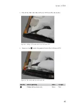
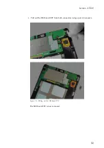
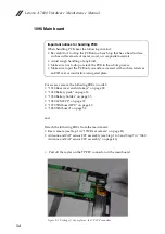
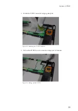
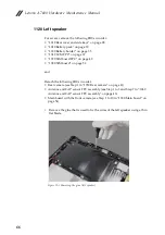
7.
Remove screws
on the main board.
Figure 9-7. The screws on the main board
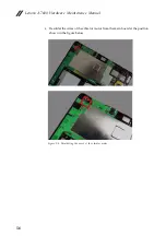
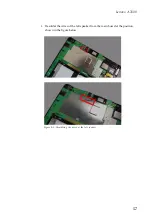
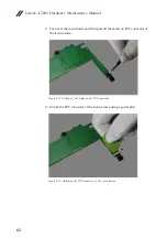
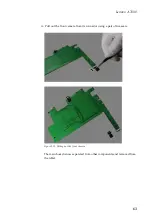
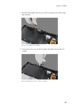
8.
Release the main board from the lock at the position shown in the figure
below.
Figure 9-8. Releasing the lock of the main board (first place)
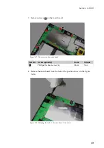
Part No.
Screw (quantity)
Color
Torque
Phillips flat head screw (4)
Silver
N/A
a
a
Содержание a7600
Страница 1: ...Lenovo A7600 Hardware Maintenance Manual ...
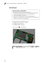
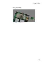
Страница 57: ...Lenovo A7600 53 2 Remove the SIM board Figure 8 2 The removed SIM board ...
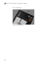
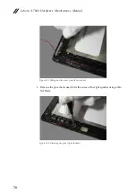
Страница 72: ...Lenovo A7600 Hardware Maintenance Manual 68 4 Remove the left speaker Figure 12 4 The removed left speaker ...
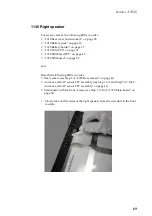
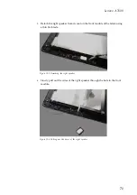
Страница 76: ...Lenovo A7600 Hardware Maintenance Manual 72 5 Remove the right speaker Figure 13 5 The removed right speaker ...
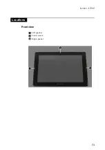
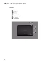
Страница 77: ...Lenovo A7600 73 Front view Left speaker Front camera Right speaker Locations ...


