


Lenovo A7600 Hardware Maintenance Manual
54
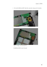
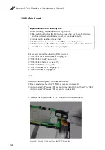
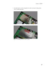
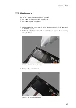
1090 Main board
For access, remove the following FRUs in order:
• “1010 Rear cover and side keys” on page 28
• “1020 Battery pack” on page 33
• “1030 Battery holder” on page 35
• “1040 LCM FPC” on page 37
• “1070 SIM board FPC” on page 49
• “1080 SIM board” on page 52
and
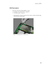
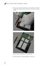
Detach the following FRUs from the main board:
• Rear camera (see Step 1 in “1050 Rear camera” on page 41)
• Antenna and CAP sensor FPC assembly (see Step 1 to 3 and Step 7 in “1060
Antenna and CAP sensor FPC assembly” on page 43)
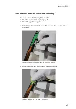
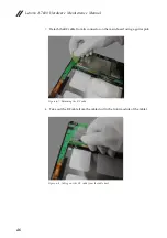
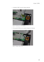
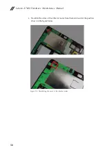
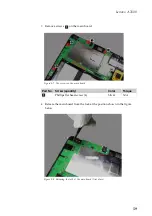
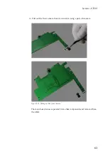
1.
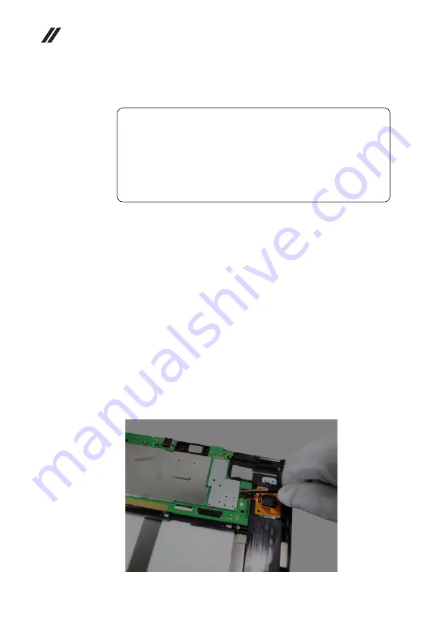
Peel off the mylar on the TP FPC connector on the main board.
Figure 9-1. Peeling off the mylar on the TP FPC connector
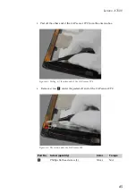
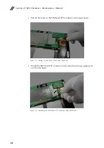
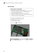
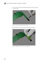
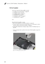
Important notices for handling PCB:
When handling PCB, bear the following in mind:
• Be careful not to drop the PCB onto a bench top that has a hard surface,
such as surface made of metal, wood, or composite materials.
• Avoid rough handling of any kind.
• Make sure not to drop or stack the PCB in the whole process.
• Make sure to put the PCB only on surface covered with such materials as
an ESD mat or conductive corrugated plate.
Содержание a7600
Страница 1: ...Lenovo A7600 Hardware Maintenance Manual ...
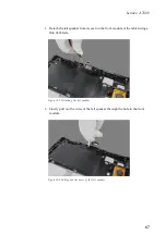
Страница 57: ...Lenovo A7600 53 2 Remove the SIM board Figure 8 2 The removed SIM board ...
Страница 72: ...Lenovo A7600 Hardware Maintenance Manual 68 4 Remove the left speaker Figure 12 4 The removed left speaker ...
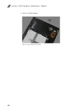
Страница 76: ...Lenovo A7600 Hardware Maintenance Manual 72 5 Remove the right speaker Figure 13 5 The removed right speaker ...
Страница 77: ...Lenovo A7600 73 Front view Left speaker Front camera Right speaker Locations ...


