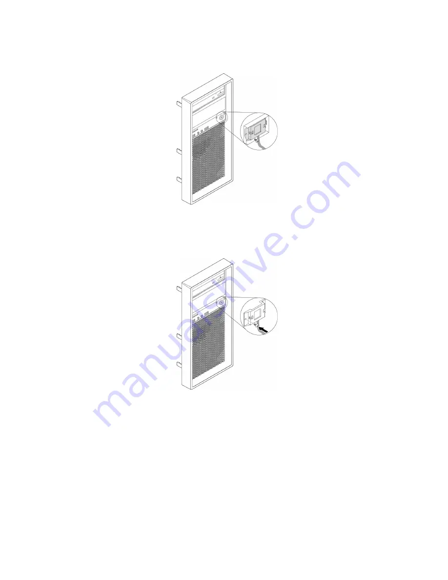
5. Remove the screw that secures the power button to the front bezel. Then, remove the power button
from the front bezel.
Figure 11. Removing the power button
6. Align the screw hole in the power button with the corresponding hole in the front bezel. Then install the
screw to secure the power button to the front bezel.
Figure 12. Installing the power button
7. Connect the power button cable to the front-bezel connector on the system board. See “Parts on the
8. Reinstall the front bezel. See “Front bezel” on page 63.
What to do next:
• To work with another piece of hardware, go to the appropriate section.
• To complete the installation or replacement, go to “Completing the parts replacement” on page 108.
PCIe card
Attention:
Do not open your computer or attempt any repair before reading and understanding the “Read
this first: Important safety information” on page v.
64
P520c User Guide
Содержание 30BX
Страница 1: ...P520c User Guide Machine Types 30BY 30BX and 30C0 ...
Страница 5: ...Appendix H Trademarks 133 Copyright Lenovo 2017 iii ...
Страница 6: ...iv P520c User Guide ...
Страница 14: ...xii P520c User Guide ...
Страница 30: ...16 P520c User Guide ...
Страница 42: ...28 P520c User Guide ...
Страница 48: ...34 P520c User Guide ...
Страница 62: ...48 P520c User Guide ...
Страница 124: ...110 P520c User Guide ...
Страница 128: ...114 P520c User Guide ...
Страница 130: ...116 P520c User Guide ...
Страница 132: ...118 P520c User Guide ...
Страница 140: ...126 P520c User Guide ...
Страница 142: ...Ukraine RoHS India RoHS RoHS compliant as per E Waste Management Rules Taiwan RoHS 128 P520c User Guide ...
Страница 144: ...4 Follow the instructions on the screen 130 P520c User Guide ...
Страница 146: ...132 P520c User Guide ...
Страница 148: ...134 P520c User Guide ...
Страница 149: ......
Страница 150: ......


