background image

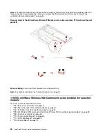
Note:

For computer models with the 5G mmWave Wireless WAN card, you need to do calibration after you 

remove, replace or reassemble the antenna bracket. For details, see “5G mmWave calibration (for selected 
models)” on page 54.

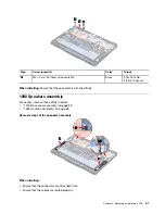
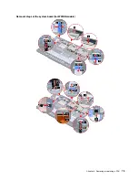
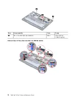
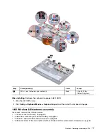
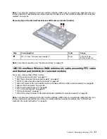
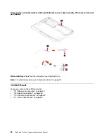
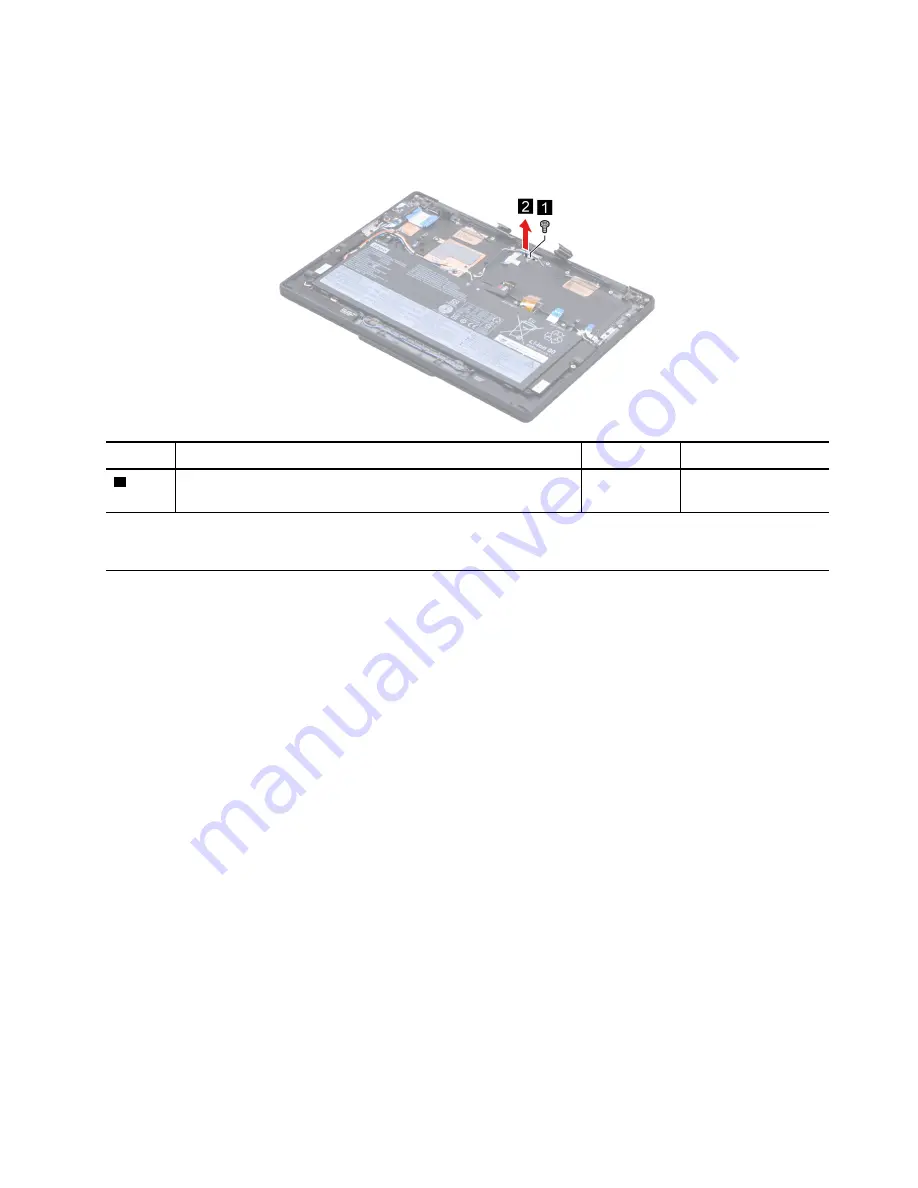
Removal steps of the 5G mmWave Wireless WAN antenna bracket (middle)

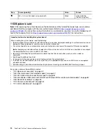
Step

Screw (quantity)

Color

Torque

1

M2 × 2.5 mm, flat-head, nylon-coated (1)

Black

0.18±0.015 Nm 
(1.85±0.15 kgf-cm)

Note:

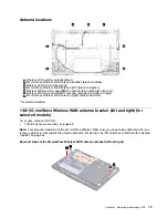
For antenna locations, see “Antenna locations” on page 73.

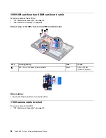
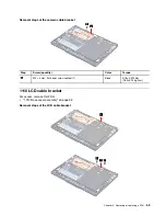
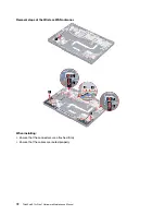
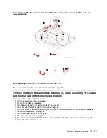
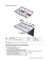
1200 5G mmWave Wireless WAN antenna kit, cable assembly, FFC cable 
and thermal pad (middle) (for selected models)

For access, remove these FRUs in order: 
•  “1010 Base cover assembly” on page 59
•  “1030 Thermal bracket (for selected models)” on page 61
•  “1040 M.2 solid-state drive and thermal pad” on page 62
•  “1050 5G Wireless WAN card and 5G mmWave Wireless WAN card (for selected models)” on page 63
•  “1060 Heatsink assembly” on page 65
•  “1100 Camera cable bracket” on page 68
•  “1110 LCD cable bracket” on page 69
•  “1150 System board” on page 74
•  “1190 5G mmWave Wireless WAN antenna bracket (middle) (for selected models)” on page 80

Note:

For computer models with the 5G mmWave Wireless WAN card, you need to do calibration after you 

remove, replace or reassemble the antenna kit, cables and thermal pad. For details, see “5G mmWave 
calibration (for selected models)” on page 54.

Chapter 8

.

Removing or replacing a FRU

81

Содержание 21BX001LGE

Страница 1: ...ThinkPad X13s Gen 1 Hardware Maintenance Manual ...

Страница 2: ...Lenovo 2022 LIMITED AND RESTRICTED RIGHTS NOTICE If data or software is delivered pursuant to a General Services Administration GSA contract use reproduction or disclosure is subject to restrictions set forth in Contract No GS 35F 05925 ...

Страница 3: ...mode 29 Hibernation mode 30 Symptom to FRU index 30 Numeric error codes 31 Error messages 32 No beep symptoms 32 LCD related symptoms 33 Intermittent problems 34 Undetermined problems 34 Chapter 5 Special keys 35 Chapter 6 Locations 37 Locating computer controls and connectors 37 Front view 37 Side view 39 Bottom view 40 Rear view 41 Locating FRUs and CRUs 42 Major FRUs and CRUs 43 Miscellaneous p...

Страница 4: ...Wave Wireless WAN antenna kit cable assembly FFC cable and thermal pad right for selected models 78 1180 5G mmWave Wireless WAN antenna kit cable assembly FFC cable and thermal pad left for selected models 79 1190 5G mmWave Wireless WAN antenna bracket middle for selected models 80 1200 5G mmWave Wireless WAN antenna kit cable assembly FFC cable and thermal pad middle for selected models 81 1210 L...

Страница 5: ...s who are familiar with products Use this manual along with the advanced diagnostic tests to troubleshoot problems effectively Depending on the model some hardware configuration and software programs might not be available on the computer Some statements in this manual might not be applicable to the computer Before servicing a product be sure to read all the information under Chapter 1 Safety info...

Страница 6: ...iv ThinkPad X13s Gen 1 Hardware Maintenance Manual ...

Страница 7: ...ians and the customer s personnel are not in a hazardous position Place removed covers and other parts in a safe place away from all personnel while you are servicing the machine Keep your tool case away from walk areas so that other people will not trip over it Do not wear loose clothing that can be trapped in the moving parts of a machine Ensure that your sleeves are fastened or rolled up above ...

Страница 8: ...ck CAUTION An electrical shock can occur only when there is a complete circuit By observing the above rule you may prevent a current from passing through your body When using testers set the controls correctly and use the approved probe leads and accessories for that tester Stand on suitable rubber mats obtained locally if necessary to insulate you from grounds such as metal floor strips and machi...

Страница 9: ... Disconnect the power cord 3 Check the power cord for a A third wire ground connector in good condition Use a meter to measure third wire ground continuity for 0 1 ohm or less between the external ground pin and the frame ground b The power cord should be the authorized type specified for your computer Go to https support lenovo com partslookup c Insulation must not be frayed or worn 4 Check for c...

Страница 10: ...rement Note The use of a grounding system to guard against ESD damage is desirable but not necessary Attach the ESD ground clip to any frame ground ground braid or green wire ground When working on a double insulated or battery operated system use an ESD common ground or reference point You can use coax or connector outside shells on these systems Use the round ground prong of the ac plug on ac op...

Страница 11: ...DANGER DANGER DANGER DANGER DANGER DANGER Chapter 1 Safety information 5 ...

Страница 12: ...DANGER 6 ThinkPad X13s Gen 1 Hardware Maintenance Manual ...

Страница 13: ...PERIGO Chapter 1 Safety information 7 ...

Страница 14: ...PERIGO PERIGO PERIGO PERIGO 8 ThinkPad X13s Gen 1 Hardware Maintenance Manual ...

Страница 15: ...PERIGO PERIGO PERIGO DANGER DANGER Chapter 1 Safety information 9 ...

Страница 16: ...DANGER DANGER DANGER DANGER DANGER 10 ThinkPad X13s Gen 1 Hardware Maintenance Manual ...

Страница 17: ...DANGER VORSICHT VORSICHT VORSICHT VORSICHT Chapter 1 Safety information 11 ...

Страница 18: ...VORSICHT VORSICHT VORSICHT VORSICHT 12 ThinkPad X13s Gen 1 Hardware Maintenance Manual ...

Страница 19: ...Chapter 1 Safety information 13 ...

Страница 20: ...14 ThinkPad X13s Gen 1 Hardware Maintenance Manual ...

Страница 21: ...Chapter 1 Safety information 15 ...

Страница 22: ...16 ThinkPad X13s Gen 1 Hardware Maintenance Manual ...

Страница 23: ...Chapter 1 Safety information 17 ...

Страница 24: ...18 ThinkPad X13s Gen 1 Hardware Maintenance Manual ...

Страница 25: ...Chapter 1 Safety information 19 ...

Страница 26: ...20 ThinkPad X13s Gen 1 Hardware Maintenance Manual ...

Страница 27: ...before completing the service action To download software fixes drivers and UEFI BIOS go to https support lenovo com and follow the instructions on the screen Use the following strategy to prevent unnecessary expense for replacing and servicing FRUs If you are instructed to replace a FRU but the replacement does not correct the problem reinstall the original FRU before you continue Some computers ...

Страница 28: ... the default country code is WW example 20AACTO1WW Special bid model This model is a unique configuration that has been negotiated between Lenovo and the customer A unique MTM consists of a 4 character MT a 4 character model and a numeric 2 character country code is provided to the customer to place orders example 20AA000955 The country code assigned is numeric and does not designate a specific co...

Страница 29: ...adiation ESD or software errors Consider replacing a FRU only when a problem recurs If you suspect that a FRU is defective clear the error log and run the test again If the error does not recur do not replace the FRU Be careful not to replace a nondefective FRU What to do first When you return a FRU you must include the following information in the parts exchange form or parts return form that you...

Страница 30: ...ad products The use of non ThinkPad products prototype cards or modified options can lead to false indications of errors and invalid system responses 1 Identify the failing symptoms in as much detail as possible 2 Verify the symptoms Try to re create the failure by running the diagnostic test or by repeating the operation Diagnosing problems Many computer problems can be solved without outside ass...

Страница 31: ...r is functional do the following 1 Turn off the computer 2 Connect the ac power adapter 3 Turn on the computer If the computer can be turned on it means that either the battery or the ac power adapter is functional 4 Insert a straightened paper clip into the emergency reset hole to reset the computer If the computer is still powered on it means that the ac power adapter is functional 5 Turn off th...

Страница 32: ...use your computer before you must charge the battery To check whether the battery charges properly during operation do the following 1 Discharge the battery to 50 or lower 2 Connect the computer to ac power to charge the battery If the battery status icon in the Windows notification area indicates that the battery is not charging remove the battery and let it return to room temperature 3 Reinstall...

Страница 33: ...management password in UEFI BIOS to prevent unauthorized access to your computer If any of these passwords has been set a prompt for it will be displayed on the screen whenever the computer is turned on The computer does not start until the password is entered Note If only a supervisor password is set the password prompt will not be displayed when the operating system is started Power on password ...

Страница 34: ...et or enter the correct system management password if no supervisor password has been set Otherwise you cannot change the configurations in the following steps 2 Select Security Password System Management Password Access Control 3 Follow the on screen instructions If you have set both the supervisor password and the system management password the supervisor password overrides the system management...

Страница 35: ...assword has been set and is known to the service technician do the following to remove the system management password 1 Turn on the computer 2 When the ThinkPad logo is displayed immediately press F1 3 Type the supervisor password to enter the ThinkPad Setup program 4 Select Security 5 Select Password 6 Select System Management Password 7 Type the current supervisor password in the Enter Current P...

Страница 36: ...wer button Also the computer goes into hibernation mode automatically after a period of inactivity specified in power plan settings When the power is turned on the computer returns from hibernation mode and resumes operation The hibernation file in the boot record on the solid state drive is read and system status is restored from the solid state drive Symptom to FRU index This section contains fo...

Страница 37: ...place the system board 0190 Critical low battery error 1 Charge the battery 2 Replace the battery 0191 System Security Invalid Remote Change requested 1 Run the ThinkPad Setup program and then save current setting by pressing F10 2 Replace the system board 0199 System Security Security password retry count exceeded 1 Run the ThinkPad Setup program The retry count will be reset Then save the curren...

Страница 38: ...arge Please replace the battery with the correct Lenovo battery for this system Press the ESC key to continue Replace the battery This system does not support batteries that are not genuine Lenovo made or authorized The system will continue to boot but may not charge unauthorized batteries Press the ESC key to continue Attention Lenovo has no responsibility for the performance or safety of unautho...

Страница 39: ...hat any replacement LCD will have zero pixel defects One pixel consists of R G B sub pixels LCD Self Test When you turn on the computer and the LCD goes black run LCD Self Test to help you determine whether the LCD functions normally To run LCD Self Test 1 Ensure that the computer is connected to ac power Then press the power button for about seven seconds to turn off the computer 2 Press Fn left ...

Страница 40: ...solate the failing FRU do not isolate FRUs that have no defects Verify that all attached devices are supported by the computer Verify that the power supply being used at the time of the failure is operating correctly See Power system checkout on page 25 1 Turn off the computer 2 Visually check each FRU for damage Replace any damaged FRU 3 Remove or disconnect all of the following devices a Non Thi...

Страница 41: ...se volume Increase volume Enable disable microphones Darken display Brighten display Manage external displays Enable disable airplane mode Enable disable camera Answer incoming calls on Microsoft Teams Decline incoming calls on Microsoft Teams Customize the function of this key on the Vantage app Open Snipping Tool Toggle keyboard backlight for selected models Break operation Pause operation Scrol...

Страница 42: ... Send system request Enter sleep mode To wake up the computer press Fn or the power button Go to beginning Go to end 36 ThinkPad X13s Gen 1 Hardware Maintenance Manual ...

Страница 43: ...ls and connectors Front view Computer Vision Microphone Infrared camera Camera Touch screen Power button with or without fingerprint reader Speaker TrackPoint pointing stick Trackpad TrackPoint buttons for selected models Copyright Lenovo 2022 37 ...

Страница 44: ...38 ThinkPad X13s Gen 1 Hardware Maintenance Manual ...

Страница 45: ...Side view USB C 3 2 Gen 2 power connector USB C 3 2 Gen 2 connector Security lock slot Nano SIM card tray Audio connector for selected models Chapter 6 Locations 39 ...

Страница 46: ...Bottom view Emergency reset hole 40 ThinkPad X13s Gen 1 Hardware Maintenance Manual ...

Страница 47: ...Rear view Microphone Chapter 6 Locations 41 ...

Страница 48: ...s manual can be found at https support lenovo com Click Documentation and then follow the on screen instructions to find the manual for your product You might be required to return the defective CRU When return is required 1 return instructions a prepaid shipping label and a container will be included with the replacement CRU and 2 you might be charged for the replacement CRU if Lenovo does not re...

Страница 49: ...Major FRUs and CRUs Chapter 6 Locations 43 ...

Страница 50: ...Yes No 18 5G mmWave Wireless WAN antenna FFC cable middle No No 19 5G mmWave Wireless WAN antenna FFC cable right No No 20 5G mmWave Wireless WAN antenna FFC cable left No No 21 5G mmWave Wireless WAN antenna bracket left and right No No 22 5G mmWave Wireless WAN antenna cable assembly right No No 23 5G mmWave Wireless WAN antenna cable assembly left No No 24 5G mmWave Wireless WAN antenna kits le...

Страница 51: ...user might order it from https pcsupport lenovo com lenovorecovery though additional shipping and handling fees might apply Miscellaneous parts Table 7 Miscellaneous part FRU descriptions Self service CRU Optional service CRU Screw kit M1 2 x L2 5 black 12 M1 6 x L2 5 silver 6 M2 x L2 silver 14 M2 x L2 large flat head silver 4 M2 x L3 black 22 M2 x L3 thin head black 8 M2 5 x L4 black 12 M2 5 x L6...

Страница 52: ...erprint reader comes with the cable Connect the cable to this connector 2 Camera connector internal Camera cable The LCD unit comes with the cable Connect the cable to this connector 3 5G mmWave Wireless WAN antenna power connector middle internal 5G mmWave Wireless WAN antenna cable middle Connect one end to the 5G mmWave Wireless WAN antenna kit middle and the other end to this connector 4 LCD c...

Страница 53: ...s WAN card into this slot 12 SSD slot internal No Insert a SSD into this slot 13 P sensor connector internal P sensor cable The wireless WAN antennas kits come with the cable Connect the cable to the connector 14 Speaker connector internal Speaker cable The speaker come with the cable Connect the cable to the connector 15 SIM card board connector internal SIM card board cable Connect one end to th...

Страница 54: ...48 ThinkPad X13s Gen 1 Hardware Maintenance Manual ...

Страница 55: ... silicone grease can be applied to the surfaces of the microprocessor and heatsink to eliminate air gaps Screw notices Loose screws can cause a reliability problem In your computer this problem is addressed with special nylon coated screws that have the following characteristics They maintain tight connections They do not easily come loose even with shock or vibration They are harder to tighten Do...

Страница 56: ...bers need to remain the same throughout the life of the computer If you replace the system board you must restore the serial number of the system unit to its original value The serial number of the system unit is written on the label attached to the bottom of the computer If you cannot find the serial number of the system unit on the bottom of the computer try the following method to get the numbe...

Страница 57: ...d does not have a UUID Note For Intel models before you perform the operation ensure that the UEFI Legacy setting within the Startup menu in the ThinkPad Setup program is set to UEFI Only 1 Connect a USB memory key to the computer 2 Go to https www lenovo com maintenanceutilities and follow the instructions on the screen to create a Maintenance Key Note Only an authorized Lenovo service technician...

Страница 58: ...e the same as the machine type of the machine that had the ECA applied to it 1 Insert the latest version of LENOVO ThinkPad Hardware Maintenance Diskette or Maintenance Key and then restart the computer 2 From the main menu select 6 Set ECA Information 3 To write the ECA information select 1 Write ECA rework number from EEPROM and follow the instructions on the screen To write the box build date s...

Страница 59: ...oving a FRU move it in the direction as given by the arrow in the illustration 7 To put the new FRU in place reverse the removal procedure and follow any notes that pertain to replacement 8 When replacing a FRU use the correct screws as shown in the replacement procedures DANGER Before removing any FRU turn off the computer unplug all power cords from electrical outlets disable the built in batter...

Страница 60: ... Wireless WAN antenna kits When you remove reassemble replace it you need to do calibration 4 5G mmWave Wireless WAN antenna bracket When you remove reassemble replace it you need to do calibration 5 Thermal pads for 5G mmWave Wireless WAN antenna When you remove reassemble replace it you need to do calibration 6 Keyboard bezel assembly with keyboard When you remove reassemble replace it you need ...

Страница 61: ...m and unzip it if necessary b Execute the setup exe file as Administrator c Follow the on screen instructions to finish the installation Notes Select the Complete setup type Choose the R D plug ins to load Do not select Launch Config Files Editor or Launch QDART_5G Help d Replace the stationconfig xml file under C Qualcomm QDART Databases with the stationconfig file provided e Restart the computer...

Страница 62: ...t LE1 2 Postcs6 folder f Run the SDX55_HWID578__MTP__NR5GMMW__RFCal_v5 cxtt file g Follow the on screen instructions You will see the status shows PASS or Fail when calibration done h Analyze the log Note If the result shows Pass it means the mmWave related parts are normal If fail open the failed log and click the hyper link of the first failed item You will see TRx Device ID 0 1 2 follow the pro...

Страница 63: ...Chapter 8 Removing or replacing a FRU 57 ...

Страница 64: ...ear the Turn on fast startup check box and then click Save changes To disable the built in battery 1 Restart your computer When the logo screen is displayed immediately press F1 to enter the UEFI BIOS menu 2 Select Config Power The Power submenu is displayed 3 Select Disable built in battery and press Enter 4 Select Yes in the Setup Confirmation window The built in battery is disabled and the comp...

Страница 65: ...ly different from the ones in the following illustration The new base cover assembly FRU is shipped with a kit containing labels of several kinds Apply those labels when you replace the base cover assembly For the labels that are not shipped with the new base cover assembly peel them from the old base cover assembly and adhere them to the new one Chapter 8 Removing or replacing a FRU 59 ...

Страница 66: ...ry diagnostic test that determines if the built in battery is defective A built in battery FRU should not be replaced unless this diagnostic test shows that the battery is defective The only exception to this is if the built in battery is physically damaged or a customer is reporting a possible safety issue If the Vantage app is not installed on the computer the customer should download and instal...

Страница 67: ...15 Nm 1 1 0 05 kgf cm When installing Ensure that the connector is attached firmly Ensure that the base cover assembly is secured in place Otherwise the battery connection may fail 1030 Thermal bracket for selected models For access remove this FRU 1010 Base cover assembly on page 59 Chapter 8 Removing or replacing a FRU 61 ...

Страница 68: ...pair The M 2 solid state drive is not designed for frequent changes or replacement Before replacing the M 2 solid state drive make a backup copy of all the data that you want to keep Do not apply pressure to the M 2 solid state drive Do not touch the contact edge or circuit board of the M 2 solid state drive Otherwise the M 2 solid state drive might get damaged Do not make the M 2 solid state driv...

Страница 69: ...d 5G mmWave Wireless WAN card for selected models For access remove this FRU 1010 Base cover assembly on page 59 1030 Thermal bracket for selected models on page 61 Note For models with 5G mmWave Wireless WAN card when you replace it with a new mmWave Wireless WAN card you need to do calibration See 5G mmWave calibration for selected models on page 54 Chapter 8 Removing or replacing a FRU 63 ...

Страница 70: ...he 5G Wireless WAN card and 5G mmWave Wireless WAN card Note For computer models with 5G wireless WAN card do not include the three 5G mmWave wireless WAN antenna cables 64 ThinkPad X13s Gen 1 Hardware Maintenance Manual ...

Страница 71: ... kgf cm When installing For antenna locations see Antenna locations on page 73 Ensure that the antenna connectors are attached firmly 1060 Heatsink assembly For access remove this FRU 1010 Base cover assembly on page 59 Removal steps of the heatsink assembly Chapter 8 Removing or replacing a FRU 65 ...

Страница 72: ...or too less application of grease can cause a thermal problem due to imperfect contact with a component 1070 Power button module with or without fingerprint reader For access remove these FRUs in order 1010 Base cover assembly on page 59 1060 Heatsink assembly on page 65 Removal steps of the power button module with or without fingerprint reader 66 ThinkPad X13s Gen 1 Hardware Maintenance Manual ...

Страница 73: ...nector is attached firmly 1080 Speakers assembly For access remove these FRUs in order 1010 Base cover assembly on page 59 1060 Heatsink assembly on page 65 Removal steps of the speakers assembly When installing Ensure that the connectors are attached firmly Ensure that the cables are routed properly Chapter 8 Removing or replacing a FRU 67 ...

Страница 74: ...ps of the SIM card board and SIM card board cable Step Screw quantity Color Torque 5 M2 3 mm flat head nylon coated 3 Black 0 18 0 015 Nm 1 85 0 15 kgf cm When installing Ensure that the connectors are attached firmly 1100 Camera cable bracket For access remove this FRU 1010 Base cover assembly on page 59 68 ThinkPad X13s Gen 1 Hardware Maintenance Manual ...

Страница 75: ...antity Color Torque 1 M2 3 mm flat head nylon coated 1 Black 0 18 0 015 Nm 1 85 0 15 kgf cm 1110 LCD cable bracket For access remove this FRU 1010 Base cover assembly on page 59 Removal steps of the LCD cable bracket Chapter 8 Removing or replacing a FRU 69 ...

Страница 76: ...d trackpad cable For access remove these FRUs in order 1010 Base cover assembly on page 59 1020 Built in battery on page 60 Removal steps of the trackpad and trackpad cable Note There might exist a waterproof mylar covering the trackpad remove the mylar before replacement 70 ThinkPad X13s Gen 1 Hardware Maintenance Manual ...

Страница 77: ... to the trackpad after replacement Ensure that the connector is attached firmly 1130 Wireless WAN antennas for selected models For access remove these FRUs in order 1010 Base cover assembly on page 59 1020 Built in battery on page 60 1030 Thermal bracket for selected models on page 61 1060 Heatsink assembly on page 65 1080 Speakers assembly on page 67 Chapter 8 Removing or replacing a FRU 71 ...

Страница 78: ...Removal steps of the Wireless WAN antennas When installing Ensure that the connectors are attached firmly Ensure that the cables are routed properly 72 ThinkPad X13s Gen 1 Hardware Maintenance Manual ...

Страница 79: ...ave Wireless WAN antenna right black and white for selected models 1140 5G mmWave Wireless WAN antenna bracket left and right for selected models For access remove this FRU 1010 Base cover assembly on page 59 Note For computer models with the 5G mmWave Wireless WAN card you need to do calibration after you remove replace or reassemble the antenna brackets For details see 5G mmWave calibration for ...

Страница 80: ...sands of G forces are applied Note Dropping a system board from a height of as little as 6 inches so that it falls flat on a hard bench can subject the accelerometer to as much as 6000 G s of shock Be careful not to drop the system board on a bench top that has a hard surface such as metal wood or composite Avoid rough handling of any kind At every point in the process be sure not to drop or stack...

Страница 81: ...Removal steps of the system board for WWAN models Chapter 8 Removing or replacing a FRU 75 ...

Страница 82: ... Screw quantity Color Torque 22 M2 3 mm flat head nylon coated 3 Black 0 18 0 015 Nm 1 85 0 15 kgf cm Removal steps of the system board for non WWAN models 76 ThinkPad X13s Gen 1 Hardware Maintenance Manual ...

Страница 83: ...eyboard Mouse Keyboard Layout and then select the keyboard language 1160 Wireless LAN antenna assembly For access remove these FRUs in order 1010 Base cover assembly on page 59 1030 Thermal bracket for selected models on page 61 1040 M 2 solid state drive and thermal pad on page 62 1050 5G Wireless WAN card and 5G mmWave Wireless WAN card for selected models on page 63 Chapter 8 Removing or replac...

Страница 84: ...al pad right for selected models For access remove these FRUs in order 1010 Base cover assembly on page 59 1020 Built in battery on page 60 1030 Thermal bracket for selected models on page 61 1060 Heatsink assembly on page 65 1080 Speakers assembly on page 67 1130 Wireless WAN antennas for selected models on page 71 1140 5G mmWave Wireless WAN antenna bracket left and right for selected models on ...

Страница 85: ...e these FRUs in order 1010 Base cover assembly on page 59 1020 Built in battery on page 60 1030 Thermal bracket for selected models on page 61 1040 M 2 solid state drive and thermal pad on page 62 1050 5G Wireless WAN card and 5G mmWave Wireless WAN card for selected models on page 63 1060 Heatsink assembly on page 65 1100 Camera cable bracket on page 68 1110 LCD cable bracket on page 69 1140 5G m...

Страница 86: ...d firmly Note For antenna locations see Antenna locations on page 73 1190 5G mmWave Wireless WAN antenna bracket middle for selected models For access remove these FRUs in order 1010 Base cover assembly on page 59 1030 Thermal bracket for selected models on page 61 1040 M 2 solid state drive and thermal pad on page 62 1050 5G Wireless WAN card and 5G mmWave Wireless WAN card for selected models on...

Страница 87: ...For access remove these FRUs in order 1010 Base cover assembly on page 59 1030 Thermal bracket for selected models on page 61 1040 M 2 solid state drive and thermal pad on page 62 1050 5G Wireless WAN card and 5G mmWave Wireless WAN card for selected models on page 63 1060 Heatsink assembly on page 65 1100 Camera cable bracket on page 68 1110 LCD cable bracket on page 69 1150 System board on page ...

Страница 88: ...e connectors are attached firmly Note For antenna locations see Antenna locations on page 73 1210 LCD unit For access remove these FRUs in order 1010 Base cover assembly on page 59 1060 Heatsink assembly on page 65 1100 Camera cable bracket on page 68 1110 LCD cable bracket on page 69 82 ThinkPad X13s Gen 1 Hardware Maintenance Manual ...

Страница 89: ...er assembly on page 59 1020 Built in battery on page 60 1030 Thermal bracket for selected models on page 61 1040 M 2 solid state drive and thermal pad on page 62 1050 5G Wireless WAN card and 5G mmWave Wireless WAN card for selected models on page 63 1060 Heatsink assembly on page 65 1070 Power button module with or without fingerprint reader on page 66 1080 Speakers assembly on page 67 1090 SIM c...

Страница 90: ...rmal pad right for selected models on page 78 1180 5G mmWave Wireless WAN antenna kit cable assembly FFC cable and thermal pad left for selected models on page 79 1190 5G mmWave Wireless WAN antenna bracket middle for selected models on page 80 1200 5G mmWave Wireless WAN antenna kit cable assembly FFC cable and thermal pad middle for selected models on page 81 1210 LCD unit on page 82 Note For mo...

Страница 91: ...ublication Lenovo may make improvements and or changes in the product s and or the program s described in this publication at any time without notice The products described in this document are not intended for use in implantation or other life support applications where malfunction may result in injury or death to persons The information contained in this document does not affect or change Lenovo...

Страница 92: ... the U S and or other countries Microsoft Microsoft Teams Windows BitLocker and Cortana are trademarks of the Microsoft group of companies USB C is a registered trademark of USB Implementers Forum Wi Fi and Miracast are registered trademarks of Wi Fi Alliance All other trademarks are the property of their respective owners 86 ThinkPad X13s Gen 1 Hardware Maintenance Manual ...

Страница 93: ...aceable Unit CTO Configure To Order EAIA Enhanced Asset Information Area EEPROM Electrically Erasable Programmable Read Only Memory EFI Extensible Firmware Interface ESD Electrostatic discharge FRU Field Replaceable Unit GAV General Announce Variant IC Integrated circuits LCD Liquid Crystal Display MTM Machine type and model POST Power on self test RFID Radio frequency identification SVP Superviso...

Страница 94: ...88 ThinkPad X13s Gen 1 Hardware Maintenance Manual ...

Страница 95: ......

Страница 96: ...Part Number SP40T80538 Printed in China 1P P N SP40T80538 1PSP40T80538 ...

Отзывы: