


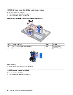
Chapter 8. Removing or replacing a FRU
This chapter provides instructions on how to remove or replace a FRU.
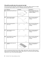
General guidelines
When removing or replacing a FRU, be sure to observe the following general guidelines:
1. Do not try to service any computer unless you have been trained and certified. An untrained person runs
the risk of damaging parts.
2. Before replacing any FRU, review Chapter 7 “FRU replacement notices” on page 49.
3. Begin by removing any FRUs that have to be removed before replacing the failing FRU. Any such FRUs
are listed at the beginning of each FRU replacement section. Remove them in the order in which they are
listed.
4. Follow the correct sequence in the steps for removing a FRU, as given in the illustrations by the numbers
in square callouts.
5. When turning a screw, turn it in the direction as given by the arrow in the illustration.
6. When removing a FRU, move it in the direction as given by the arrow in the illustration.
7. To put the new FRU in place, reverse the removal procedure and follow any notes that pertain to
replacement.
8. When replacing a FRU, use the correct screws as shown in the replacement procedures.
DANGER
Before removing any FRU, turn off the computer, unplug all power cords from electrical outlets,
disable the built-in battery, and then disconnect any interconnecting cables.
Attention:
• After replacing a FRU, do not turn on the computer until you have made sure that all screws, springs, and
other small parts are in place and none are loose inside the computer. Verify this by shaking the computer
gently and listening for rattling sounds. Metallic parts or metal flakes can cause electrical short circuits.
• The system board is sensitive to, and can be damaged by ESD. Before touching it, establish personal
grounding by touching a ground point with one hand or by using an ESD strap.
Before servicing the computer
Carefully read this topic before servicing the computer.
© Copyright Lenovo 2022
53
Содержание 21BX001LGE
Страница 1: ...ThinkPad X13s Gen 1 Hardware Maintenance Manual ...
Страница 6: ...iv ThinkPad X13s Gen 1 Hardware Maintenance Manual ...
Страница 11: ...DANGER DANGER DANGER DANGER DANGER DANGER Chapter 1 Safety information 5 ...
Страница 12: ...DANGER 6 ThinkPad X13s Gen 1 Hardware Maintenance Manual ...
Страница 13: ...PERIGO Chapter 1 Safety information 7 ...
Страница 14: ...PERIGO PERIGO PERIGO PERIGO 8 ThinkPad X13s Gen 1 Hardware Maintenance Manual ...
Страница 15: ...PERIGO PERIGO PERIGO DANGER DANGER Chapter 1 Safety information 9 ...
Страница 16: ...DANGER DANGER DANGER DANGER DANGER 10 ThinkPad X13s Gen 1 Hardware Maintenance Manual ...
Страница 17: ...DANGER VORSICHT VORSICHT VORSICHT VORSICHT Chapter 1 Safety information 11 ...
Страница 18: ...VORSICHT VORSICHT VORSICHT VORSICHT 12 ThinkPad X13s Gen 1 Hardware Maintenance Manual ...
Страница 19: ...Chapter 1 Safety information 13 ...
Страница 20: ...14 ThinkPad X13s Gen 1 Hardware Maintenance Manual ...
Страница 21: ...Chapter 1 Safety information 15 ...
Страница 22: ...16 ThinkPad X13s Gen 1 Hardware Maintenance Manual ...
Страница 23: ...Chapter 1 Safety information 17 ...
Страница 24: ...18 ThinkPad X13s Gen 1 Hardware Maintenance Manual ...
Страница 25: ...Chapter 1 Safety information 19 ...
Страница 26: ...20 ThinkPad X13s Gen 1 Hardware Maintenance Manual ...
Страница 44: ...38 ThinkPad X13s Gen 1 Hardware Maintenance Manual ...
Страница 46: ...Bottom view Emergency reset hole 40 ThinkPad X13s Gen 1 Hardware Maintenance Manual ...
Страница 47: ...Rear view Microphone Chapter 6 Locations 41 ...
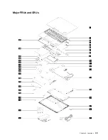
Страница 49: ...Major FRUs and CRUs Chapter 6 Locations 43 ...
Страница 54: ...48 ThinkPad X13s Gen 1 Hardware Maintenance Manual ...
Страница 63: ...Chapter 8 Removing or replacing a FRU 57 ...
Страница 81: ...Removal steps of the system board for WWAN models Chapter 8 Removing or replacing a FRU 75 ...
Страница 94: ...88 ThinkPad X13s Gen 1 Hardware Maintenance Manual ...
Страница 95: ......
Страница 96: ...Part Number SP40T80538 Printed in China 1P P N SP40T80538 1PSP40T80538 ...