


Page 41
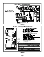
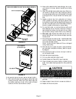
G60UHV(X) BURNER & HEAT EXCHANGER REMOVAL
FIGURE 28
HEAT EXCHANGER
BURNER BOX
ASSEMBLY
GAS VALVE
ASSEMBLY
GASKET
NOx INSERTS
(X models only)
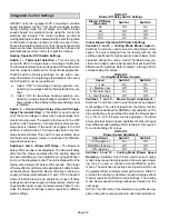
FIGURE 29
NOx INSERT
10− Repeat procedure for each heat exchanger section.
11− After each of the top heat exchanger sections has been
cleaned, insert the brush end of the cable snake into
the bottom openings of each of the heat exchanger
sections and clean as described in step 8.
12− Remove the cable from the heat exchanger. Use a vac-
uum cleaner to remove debris knocked loose during
cleaning.
13− Attach the exhaust end (positive pressure) of the vacu-
um cleaner to the top of the heat exchanger section.
Any loose debris will be forced to the bottom of the heat
exchanger section. Vacuum debris from bottom open-
ings.
14− Replace collector box and combustion air inducer.
Check gaskets for damage. Damaged gaskets must
be replaced to avoid heat exchanger leaks. Replace all
screws to the collector box and combustion air inducer.
Failure to replace all screws may cause leaks.
15− To clean the burner, run a vacuum cleaner with a soft
brush attachment over the face of burners. Visually in-
spect inside the burners and crossovers for any block-
age caused by foreign matter. Remove any blockage.
16−
NOx units only
−
Reattach the NOx inserts to the cor-
bels at the entrance to each heat exchanger opening.
See figure 29.
17− Re−install gasket and burner box / manifold assembly
onto the vestibule panel. Replace burner box cover
and re−secure using screws.
NOTE − Gasket must be replaced if it was damaged
during disassembly.
18− Reconnect wires to pressure switch, roll−out switches,
gas valve and combustion air inducer. Refer to unit wir-
ing diagram.
19− Re−install top cap and re−secure vent pipe to combus-
tion air inducer outlet.
20− Reconnect gas supply piping.
21− Turn on power and gas supply to unit.
22− Set thermostat and check for proper operation.
23− Check all piping connections, factory and field, for gas
leaks. Use a leak detecting solution or other preferred
means.
CAUTION
Some soaps used for leak detection are corrosive to
certain metals. Carefully rinse piping thoroughly af-
ter leak test has been completed. Do not use
matches, candles, flame or other sources of ignition
to check for gas leaks.
24− If a leak is detected, shut gas and electricity off and re-
pair leak.
25− Repeat steps 23 and 24 until no leaks are detected.
26− Replace front access panel.


