Page 32
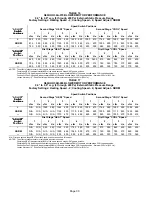
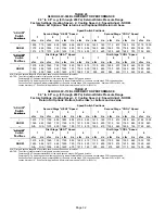
TABLE 20
G60UHV−60C−090 BLOWER MOTOR PERFORMANCE
0.0" to 0.8" w.g. (0 through 200 Pa) External Static Pressure Range
Factory Settings: Heating Speed − 2; Cooling Speed − 4; Speed Adjust − NORM.
Return Air Options: Side return air with optional RAB return air base.
Speed Switch Positions
ADJUST"
Switch
Second Stage HEAT" Speed
Second Stage COOL" Speed
Switch
Positions
1
2
3
4
1
2
3
4
Positions
cfm
L/s
cfm
L/s
cfm
L/s
cfm
L/s
cfm
L/s
cfm
L/s
cfm
L/s
cfm
L/s
+
1505
710
1690
800
1900
895
2090
985
1625
765
1715
810
1940
915
2175 1030
NORM
1370
645
1535
725
1745
825
1915
905
1450
685
1560
735
1765
835
1945
915
1215
575
1375
650
1535
725
1705
805
1310
620
1405
660
1595
755
1795
850
ADJUST"
First Stage HEAT" Speed
First Stage COOL" Speed
ADJUST"
Switch
P
iti
1
2
3
4
1
2
3
4
S
tc
Positions
cfm
L/s
cfm
L/s
cfm
L/s
cfm
L/s
cfm
L/s
cfm
L/s
cfm
L/s
cfm
L/s
+
1370
650
1540
725
1745
825
1925
910
1130
530
1205
570
1360
645
1530
720
NORM
1240
585
1405
665
1565
740
1765
830
1025
485
1100
520
1240
585
1385
655
1135
535
1265
600
1420
670
1560
735
900
425
985
465
1115
525
1240
585
N/A − First and second stage HEAT positions shown cannot be used on this model.
NOTES − The effect of static pressure is included in air volumes shown.
First stage HEAT is approximately
91%
of the same second stage HEAT speed position.
First stage COOL (two−stage air conditioning units only) is approximately
70%
of the same second stage COOL speed position.
Continuous Fan Only speed is approximately
38%
of the same second stage COOL speed position − minimum 500 cfm (235 L/s).
Lennox Harmony III
t
Zone Control Applications − Minimum blower speed is 478 cfm (225 L/s).
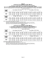
TABLE 21
G60UHV−60C−110 BLOWER MOTOR PERFORMANCE
0.0" to 0.8" w.g. (0 through 200 Pa) External Static Pressure Range
Factory Settings: Heating Speed − 2; Cooling Speed − 4; Speed Adjust − NORM.
Return Air Options: Bottom; both sides; or bottom and one side.
Speed Switch Positions
ADJUST"
Switch
Second Stage HEAT" Speed
Second Stage COOL" Speed
Switch
Positions
1
2
3
4
1
2
3
4
Positions
cfm
L/s
cfm
L/s
cfm
L/s
cfm
L/s
cfm
L/s
cfm
L/s
cfm
L/s
cfm
L/s
+
1510
715
1700
805
1895
895
2105
995
1610
760
1730
815
1955
920
2185 1030
NORM
1365
645
1545
730
1725
815
1915
905
1460
690
1575
745
1780
840
1995
940
N/A
N/A
1375
650
1545
730
1715
810
1295
610
1395
660
1600
755
1780
840
ADJUST"
First Stage HEAT" Speed
First Stage COOL" Speed
ADJUST"
Switch
P
iti
1
2
3
4
1
2
3
4
S
tc
Positions
cfm
L/s
cfm
L/s
cfm
L/s
cfm
L/s
cfm
L/s
cfm
L/s
cfm
L/s
cfm
L/s
+
1370
650
1560
735
1750
825
1925
910
1125
530
1190
565
1350
640
1530
720
NORM
1245
585
1410
665
1590
750
1760
830
1015
480
1090
515
1230
580
1360
640
N/A
N/A
1255
595
1420
670
1575
745
900
425
975
460
1110
525
1235
580
N/A − First and second stage HEAT positions shown cannot be used on this model.
NOTES − The effect of static pressure is included in air volumes shown.
First stage HEAT is approximately
91%
of the same second stage HEAT speed position.
First stage COOL (two−stage air conditioning units only) is approximately
70%
of the same second stage COOL speed position.
Continuous Fan Only speed is approximately
38%
of the same second stage COOL speed position − minimum 500 cfm (235 L/s).
Lennox Harmony III
t
Zone Control Applications − Minimum blower speed is 483 cfm (230 L/s).


