


9
NOTE: DIAGRAMS & ILLUSTRATIONS ARE NOT TO SCALE.
LENNOX HEARTH PRODUCTS • MERIT PLUS
®
B-VENT GAS FIREPLACES (MPB33/35/40/45) • INSTALLATION INSTRUCTIONS
.
o
N
l
e
d
o
M
A
B
C
D
E
F
G
.
n
i
5
3
8
/
1
-
8
/
1
-
2
3
9
1
2
/
1
-
9
2
5
3
8
/
1
-
8
/
-
6
1
/
7
-
2
5
8-3/4
13
330
406
16
406
16
406
16
m
m
2
9
8
6
1
8
3
8
4
9
4
7
2
9
8
2
3
6
6
1
3
7
2
1
222
.
n
i
8
/
1
-
0
4
8
/
1
-
7
3
4
2
2
/
1
-
4
3
8
/
1
-
0
4
8
/
7
-
9
2
1
6
1
/
5
1
-
4
5
8-3/4
m
m
9
1
0
1
3
4
9
0
1
6
6
7
8
9
1
0
1
9
5
7
9
7
3
7
2
1
22
2
.
n
i
8
/
1
-
0
4
8
/
1
-
7
3
4
2
2
/
1
-
9
3
8
/
1
-
5
4
8
/
7
-
4
3
6
1
/
7
-
7
1
6
8-3/4
m
m
6
4
1
1
3
4
9
0
1
6
3
0
0
1
6
4
1
1
6
8
8
3
4
4
2
5
1
222
MPB33
MPB35
MPB40
MPB45
in.
mm
33-1/8
841
432
765
841
699
21-1/2
33-1/8
4
546
102
273
27-1/2
17
30-1/8
24-7/8
621
12-7/16
10-3/4
J
K
H
6-1/2
165
Schedule 40 - Black Iron Pipe
Inside Diameter (Inches)
Schedule 40 Pipe
Length (feet)
Natural
Gas
Propane
Gas
0 - 10
1/2"
3/8"
10 - 40
1/2"
1/2"
40 - 100
1/2"
1/2"
100 - 150
3/4"
1/2"
150 - 200
3/4"
1/2"
Table 6
PROPER SIzING OF GAS LINE
Properly size and route the gas supply line
from the supply regulator to the area where the
appliance is to be installed per requirements
outlined in the National Fuel Gas Code, ANSI
Z223.1 (NFPA 54) - latest edition (USA) or CAN/
CGA-B149.1 - latest edition (Canada).
Never use galvanized or plastic pipe. Refer to
Table 6
for proper sizing of the gas supply
line, if black iron pipe is being used. Gas lines
must be routed, constructed and made of
materials that are in strict accordance with
local codes and regulations. We recommend
that a qualified individual such as a plumber
or gas fitter be hired to correctly size and route
the gas supply line to the appliance. Installing
a gas supply line from the fuel supply to the
appliance involves numerous considerations of
materials, protection, sizing, locations, controls,
pressure, sediment, and more. Certainly no one
unfamiliar and unqualified should attempt sizing
or installing gas piping.
NOTES:
•
All appliances are factory-equipped with a
flexible gas line connector and 1/2" shutoff
valve
(see
Figure 21
on
Page 13
)
.
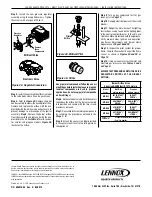
STEP 2. ROUTING GAS LINE
Route a 1/2" (13 mm) gas line as shown in
Figure
13
. Gas lines must be routed, constructed and
made of materials that are in strict accordance
with local codes and regulations. The appliance,
as set up at the factory, is best suited for use
with a gas line routed from the left side. The gas
line may however be alternately routed from the
right side. All appliances are factory-equipped
with a flexible gas line connector and 1/2" shutoff
valve
(see
Step 6 on Page 12
).
•
See
Massachusetts Requirements
on
Page
4
for additional requirements for installations
in the state of Massachusetts in the USA.
•
The gas supply line SHOULD NOT be
connected to the appliance until
Step 6
on
Page 12
).
•
A pipe joint compound rated for gas should be
used on the threaded joints.
Ensure propane
resistant compounds are used in propane
applications
. Be very careful that the pipe
compound does not get inside the pipe.
•
It is recommended to install a sediment trap
in the supply line as close as possible to the
appliance.
•
Check with local building official for local code
requirements.
F
E
B
D
C
G
T op View
FRAMING
STANDOFFS
(Top, Sides,
and Rear)
Front View
3 (76)
A
J
H
Flue Outlet For B-V ent Connection
OPTIONAL ELECTRICAL
INLET KNOCKOU T
REQUIRING A FIELD
PROVIDED JUNCTION
BOX (Either Side)
GAS INLET
(Either Side
and bottom )
NOTE - Hood shown
as positioned
in louvered
front model.
ELECTRICAL INLET
2-3/4 x 2 (70 x 51) COVER
PLA TE with KNOCKOUT)
K
1/2 (13)
3 (76)
1-3/8
(35)
(140)
5-1/2
9-3/8
(238)
2
(53)
Right Side View
(140)
5-1/2
9-3/8
(238)
1-3/8
(35)
Left Side View
GAS INLET
(See Also
Right Side View
)
ELECTRICAL INLET
(See Also
Right Side View )
3
(76)
OUTSIDE AIR
SHUTTER
8-15/16
(227)
7-3/8
(187)
ELECTRICAL
INLET
(Optional)
Figure 12 - Fireplace Specifications
3"
(76 mm)
6-1/2"
(152 mm)
Pipe Coupling
(Recommended)
Also see
Figure 11.
Figure 13 - Gas Line Routing