Lennox MPB33CNE Скачать руководство пользователя страница 10

10

NOTE: DIAGRAMS & ILLUSTRATIONS ARE NOT TO SCALE.

LENNOX HEARTH PRODUCTS  •  MERIT PLUS

®

 B-VENT GAS FIREPLACES (MPB33/35/40/45)  •  INSTALLATION INSTRUCTIONS

IMPORTANT: If propane is used, be aware that 

if tank size is too small (i.e. under 100-lbs, if 

this is the only gas appliance in the dwelling. 

Ref. NPFA 58), there may be loss of pressure, 

resulting in insufficient fuel delivery (which 

can result in sooting,  severe delayed ignition 

or other malfunctions). Any damage resulting 

from an improper installation, such as this, 

is not covered under the limited warranty.

STEP 3. INSTALLING VENT SYSTEM 

These instructions should be used as a 

guideline and do not supersede local codes 

in any way. Install venting according to local 

codes, these instructions, the current National 

Fuel Gas Code (ANSI-z223.1) in the USA or 

the current standards of CAN/CGA-B149.1 

in Canada. 

Ensure clearances are in accordance with 

local installation codes and the requirements 

of the gas supplier.

Dégagement conforme aux codes d'installa-

tion locaux et aux exigences du foumis-

seunde gaz.

Use only approved vent components (see 

Approved Vent Components

 on 

Page 2).

These fireplaces must be vented vertically to 

the outside.

Refer to 

Figure 14,

 and slip the first section 

of B-Vent over  the fireplace flue outlet and 

secure with sheet metal screws (# 8 or larger), 

then install the remainder of the B-Vent vertically 

to the outside. Minimum overall height of the 

vent system and appliance must be 10' (2.54 

m) vertical with no offset, or 12' (3.7 m) when 

an offset up to 45 degrees from the vertical is 

used; or 15' (4.6 m) when an offset is greater 

than 45 degrees and up to 60 degrees (see 

Figure 17

).

The offset may start at the fireplace flue collar. 

The maximum overall height of the vent system 

and appliance should not exceed 40 feet.  

Install the B-vent system in accordance with 

the vent manufacturer's instructions.

Required Pipe Diameter:

MPB33 series: 

Requires 4" (102 mm) 

MPB35 series: 

Requires 5" (127 mm) 

MPB40 series: 

Requires 5" (127 mm) 

MPB45 series: 

Requires 6" (152 mm)

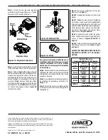
Figure 14 - Initial B-Vent Installation

Type B-Vent - 4" (102 mm) for MPB33 Models, 

5" (127 mm) for MPB35 / 40 Models or 6" 

(152 mm) for MPB45 Models

Securing 

Screws

Flue Outlet 

Collar

Refer to the vent manufacturers installation 

instructions for variations of venting techniques. 

If common venting of several units is contem-

plated, it should be discussed with an architect 

and the local Building Department.

Do not place insulation materials within 1" of 

the gas vent system.

Back View

Of Appliance

10 ft.

 Minimum

Back View

Of Appliance

*12 ft. Min.

**15 ft. Min.

*with an offset up to 45 degrees

** with an offset greater than 45

degrees and up to 60 degrees

Vertical 

Installations

Back View

Of Appliance

10 ft.

 Minimum

Back View

Of Appliance

*12 ft. Min.

**15 ft. Min.

*with an offset up to 45 degrees

** with an offset greater than 45

degrees and up to 60 degrees

Offset 

Installations

The maximum overall height of the vent system 

and appliance should not exceed 40 feet.

Figure 17 - Vent System Installation

       CAUTION  

This appliance cannot be vented 

horizontally.

USE ONLY APPROVED B-VENT DIAMETER

MPB33, MPB35, MPB40 and MPB45 series 

fireplaces must be vertically vented using 

listed type-B, double-walled vent pipe with 

the proper diameter as listed below and a 

listed vent termination.

Содержание MPB33CNE

Страница 1: ... SURFACE VITRÉE CHAUDE PEUT CAUSER DES BRÛLURES LAISSER REFROIDIR LA SURFACE VITRÉE AVANT D Y TOUCHER NE PERMETTEZ JAMAIS À UN ENFANT DE TOUCHER LA SURFACE VITRÉE EL VIDRIO CALIENTE CAUSARÁ QUEMADURAS USTED DEBE NUNCA TOCAR EL VIDRIO CALIENTE LOS NIÑOS DEBEN NUNCA TOCAR EL VIDRIO Do not store or use gasoline or other flammable vapors and liquids in the vicinity of this or any other appliance WHAT ...

Страница 2: ...on 5 Vent Termination Clearances 5 Appliance and Vent Clearances 6 Pre Installation Steps 7 Typical Installation Sequence 7 Detailed Installation Steps 7 Step 1 Framing 7 Framing Specifications 8 Fireplace Specifications 9 Step 2 Routing Gas Line 9 Step 3 Installing Vent System 10 Step 4 Field Wiring 11 Step 5 Wiring Optional Forced Air Blower Kit 12 Step 6 Connecting Gas Line 12 Step 7 Installing...

Страница 3: ...nal Safety Standards and are tested and listed by OMNI Test Laboratories Inc Report No 116 F 36d 5 toANSIZ21 50b 2009 inCanada CSA 2 22b 2009 and CAN CGA 2 17 M91 R2009 in both USA and Canada as vented gas fireplaces Bothmillivoltandelectronicversionsofthese appliances may be used in bedrooms only when the room is an unconfined space as defined by the National Fuel Gas Code Use in bedrooms may not...

Страница 4: ...onin the US state of Massachusetts if the following additional requirements are met Install this appliance in accordance with Massachusetts Rules and Regulations 248 C M R Installation and repair must be done by a plumber or gas fitter licensed in the Com monwealth of Massachusetts The flexible gas line connector used shall not exceed 36 inches 92 centimeters in length The individual manual shut o...

Страница 5: ...d out of traffic and away from furniture and draperies Figure 3 En raison des températures élevées l appareil devrait être installé dans un endroit où il y a peu de circulation et loin du mobilier et des tentures Figure 3 The location should also be free of electrical plumbing or other heating air conditioning ducting Be aware that this is a heat producing ap pliance Objects placed above the unit ...

Страница 6: ... side of the fireplace may abutt a perpendicular wall For this type of installation the other side of the fireplace must be a flat wall to allow for proper air flow and burner operation Combustiblematerialsmayprojectbeyondone or both sides of the fireplace opening when these materials are kept within the Safe Zone illustrated in Figure 6 3 1 2 in 89mm Top View of Fireplace Combustiblematerials may...

Страница 7: ...abs one on each side located at the base of the fireplace and secure to the floor by nailing with 8d nails or equivalent see Figure 10 Anchor Tab Step 10 REMOVING AND Installing THE Glass Door Page 19 Step 11 Burner Adjustments Page 19 Adjust burner primary air shutter to achieve proper flame appearance Step 12 TESTING VENT OPERATION Page 21 Vent operation test and safety limit switch operation St...

Страница 8: ... Enclosure Including Finishing Materials if any Rough Framing Face Unfinished Shown o N l e d o M A t i n U e z i S A g n i m a r F e z i S B C D E F G H J K n i 5 3 8 1 5 3 4 1 5 3 4 1 9 1 8 5 9 1 7 5 2 1 4 3 8 2 6 1 4 6 1 9 6 8 5 0 4 m m 2 9 8 5 9 8 5 9 8 3 8 4 8 9 4 0 6 4 1 0 3 7 6 0 4 2 0 1 7 6 1 2 3 0 1 n i 8 1 0 4 4 1 0 4 4 1 0 4 4 2 8 5 4 2 6 1 3 1 1 6 6 1 1 0 3 6 1 4 6 1 9 6 2 3 1 1 3 4 m ...

Страница 9: ...lynoone unfamiliarandunqualifiedshouldattemptsizing or installing gas piping NOTES All appliances are factory equipped with a flexible gas line connector and 1 2 shutoff valve see Figure 21 on Page 13 Step 2 ROUTING Gas Line Routea1 2 13mm gaslineasshowninFigure 13 Gas lines must be routed constructed and made of materials that are in strict accordance withlocalcodesandregulations Theappliance as ...

Страница 10: ...rtical is used or 15 4 6 m when an offset is greater than 45 degrees and up to 60 degrees see Figure 17 The offset may start at the fireplace flue collar The maximum overall height of the vent system and appliance should not exceed 40 feet Install the B vent system in accordance with the vent manufacturer s instructions Required Pipe Diameter MPB33 series Requires 4 102 mm MPB35 series Requires 5 ...

Страница 11: ...TIONAL GROUND BATTERY HOLDER DFC WIRE HARNESS SPARK WIRE CABLE PILOT GROUND WIRE PILOT SENSOR CABLE HOOD IGNITER ROD FLAME SENSOR PILOT TUBE CPI SWITCH OFF O INTERMITTENT PILOT MODE ON STANDING PILOT MODE PROFLAME DFC BOARD PROFLAME VALVE ELECTRONIC PILOT ASSEMBLY B BLACK BR BROWN GY GRAY PU PURPLE R RED BL BLUE G GREEN O ORANGE W WHITE Y YELLOW WIRING COLOR CODE B B B R R W W B B B B BL BL G G O ...

Страница 12: ... the grounding prong from the plug Step 6 Connecting Gas Line Make gas line connections All codes require a shut off valve mounted in the supply line The orientation of the shut off valve should face the front see Figure 22 Figure 21 illustrates two methodsforconnectingthegassupply Theflex line method is acceptable in the U S however Canadian requirements vary depending on locality Installation mu...

Страница 13: ... DONOTterminatetheductcloserthan3 below the chimney top Outside supplemental combustion air ducting may be run upwards or vertically through framing and ceiling joists with the hood installed through an outside wall and 3 1 m belowthetermination Ductingmayalsoberun downward through floor joists and under the hometoaventilatedcrawlspacenotconsidered part of the living area of the home Outside Air C...

Страница 14: ... for MPB35 Series appliances and Figure 30 for MPB40 and MPB45 Series appliances NOTE Turn off all electricity to the appliance before you install volcanic stone embers and logs The flame should project 1 25 mm beyond the hood at all three ports see Figure 24 Replace logs if removed for pilot inspection To light the burner turn ON the remote wall switch and rotate the gas valve control knob counte...

Страница 15: ...nt door see Removing the Glass Enclosure Panel on Page 19 Step 2 Install decorative volcanic stone Sprinkle the decorative volcanic stone in a pleasing pattern The volcanic stone should be placed directly on top of the firebox bottom along the front and to the back at the right and left sides of the burner Position any optional ceramic fiber liners before placing the stone Logs should be positione...

Страница 16: ...upper end Place the left log and then the smaller left and right top logs All logs that have notches to fit over the grate tines should be positioned with these notches directly against the grate All top logs that rest on lower logs do so over flattened mounting faces in the bottom logs Properlogandtwigplacementiscriticaltoencourageoutstanding flame appearance and prevent sooting 3 2 4 5 6 1 2 3 4...

Страница 17: ... placed in the order shown Position the rear log on the brackets at the rear of the firebox with the log s notches directly over the brackets Position the right log log no 3 by inserting the pin from the rear log into the hole on its upper end Place the left log and then the smaller left and right top logs All logs that have notches to fit over the grate tines should be positioned with these notch...

Страница 18: ...ion the individual logs as shown below Logs should be placed in the order shown Position the center log on the burner first then place the glowing embers as shown in Figure 27 Place the rear log both the right and left and then the smaller left and right top logs All logs that have notches to fit over the grate tines should be positioned with these notches directly against the grate All top logs t...

Страница 19: ...t appear sooty NOTE Thefollowingchartisprovidedtoaidyou in achieving the correct air shutter adjustment for your installation Removing the Glass Enclosure Panel see Figure 31 Removethetoplouverassembly Openthelower control compartment door see Figure 22 on Page 13 by pressing in simultaneously at the left and right top corners of the door the door is hinged at the bottom Remove the bottom compartm...

Страница 20: ...position 1 Refer to Figures 32 33 and 34 for proper flame appearance To adjust the flame refer to Figure 35 and move the rod up and down the adjustment rod is located in the lower control area Position the air shutter to the factory setting as shown in Table 8 2 Light appliance follow lighting procedure on lighting label in control compartment or in the Care and Operation Instructions 3 Allow the ...

Страница 21: ...ure 37 for its location If during appliance operation the flame goes out independently of the burner on off wall switch it may be due to a blocked vent If this condition occurs the safety limit switch will activate causing the fireplace burner to shut off To reset the safety limit switch perform the following steps NOTE Allow the appliance to cool completely 7 Remove the top louver panel 8 Reset t...

Страница 22: ...de est utilisée pour contrôler le foyer nettoyez la soigneusement pour éliminer la poussière et les traces de graisse ou d huile Collez l étiquette sur le boîtier de la télécommande Figure B Choisissez la langue qui est principale ment parlée dans la résidence du propriétaire En cas de doute collez l étiquette en anglais 3 Si vous ne trouvez pas les étiquettes veuillez appeler Lennox Hearth Produc...

Страница 23: ...sembly C Remove the burner assembly with attached venturi tube Millivolt and Electronic Ignition System Appliances Step 1 SIT Systems Refer to Figure 38 and the instructions provided with the SIT Regu lator Conversion Kit Using a Torx T20 driver to remove and discard the pressure regulator mounting screws two screws for electronic models three screws for millivolt models pressure regulator tower t...

Страница 24: ...y proper burner ignition and operation See Burner Adjustments and Burner Flame Appearance on Pages 19 and 20 Step 12 Inspect the pilot system for proper flame The pilot flame should engulf the flame sensor as shown in Figures 24 and 25 on Page 14 Step 13 Using a manometer test the inlet and manifold gas pressures see Tables 2 and 3 on Page 4 ALWAYS TEST PRESSURES WITH THE VALVE REGULATOR CONTROL A...

Отзывы: