22
23
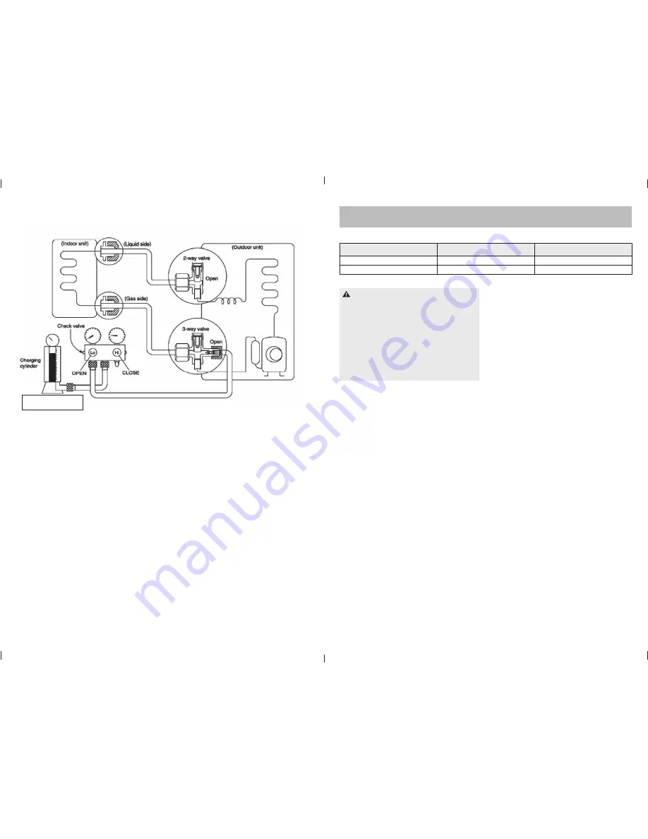
1. Connect the charge hose to the charging cylinder, open the
2-way valve and the 3-way valve. Connect the charge hose
which you disconnected from the vacuum pump to the valve at
the bottom of the cylinder. If the refrigerant is R410A, make the
cylinder bottom-up to ensure liquid charge.
2. Purge the air from the charge hose.
Open the valve at the bottom of the cylinder and press the
check valve on the charge set to purge the air (be careful of the
liquid refrigerant).
3. Put the charging cylinder onto the electronic scale and record
the weight.
4. Open the valves (Low side) on the charge set and charge the
system with liquid refrigerant. If the system cannot be charged
with the specifi ed amount of refrigerant, it can be charged a
little at a time (approximately 150g each time), operating the
air conditioner in the cooling cycle. However, one time is not
suffi cient. Wait approximately 1 minute and then repeat the
procedure.
5. When the electronic scale displays the proper weight,
disconnect the charge hose from the 3-way valve’s service
port immediately. If the system has been charged with liquid
refrigerant while operating the air conditioner, turn off the air
conditioner before disconnecting the hose.
6. Mount the valve stem caps and the service port. Use a torque
wrench to tighten the service port cap to a torque of 18Nm. Be
sure to check for gas leakage.
Procedure:
2. Refrigerant charging
Electronic scale
7. OPERATION CHARACTERISTICS
Operation Mode
Outdoor temperature (ºC)
Room temperature (ºC)
Cooling operation
0 – 50
≥
17
Heating operation
-15 – 34
≤
30
CAUTION
1. If the air conditioner is used outside the above conditions,
certain safety protection features may come into operation
and cause the unit to operate abnormally.
2. The room relative humidity should be less than 80%. If the
air conditioner operates above this fi gure, the surface of
the air conditioner may attract condensation. Please set the
vertical air fl ow louvre to its maximum angle (vertically to the
fl oor), and set fan mode to HIGH.
3. Optimum performance will be achieved whilst operating
within this temperature zone.
E963_Lennox Luna Inverter Service Manual 1c.indd 22-23
E963_Lennox Luna Inverter Service Manual 1c.indd 22-23
13/12/11 4:43 PM
13/12/11 4:43 PM


