


CLEANING TOP
FIGURE 19
CLEANING
PORTS
FIGURE 20
CLEANING INSIDE
FIGURE 21
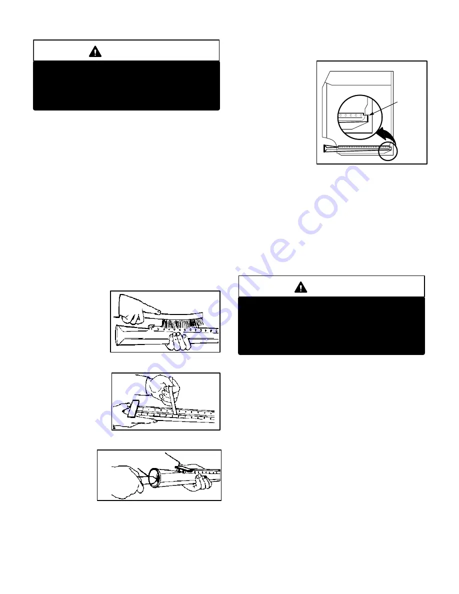
FIGURE 22
BURNER SLOT ENGAGEMENT
ENGAGE
BURNER
IN SLOT
Page 11
CAUTION
Potential for unit damage.
Use extreme care when opening damper door to
prevent permanent damage to the damper door.
Can cause damage to damper motor resulting in
improper furnace operation.
6- Remove flue restrictor over flue outlet (Ć50 only).
7- Gas manifold, gas valve and burners do not need to be
removed and can be left in place.
8- Insert a 2 ft. steel rod with a 20 in. length of chain atĆ
tached to one end into top opening of heat exchanger.
Refer to figure 18.
9- Shake rod to drop chain through clamshell into burner
cavity in bottom of heat exchanger.
10- Attach bottom of chain to 2 ft. (600 mm) rod.
11- Push and pull the rods back and forth and up and down
with a vigorous motion. The chain will dislodge the soot
and scale deposits inside the heat exchanger. Repeat
for each clamshell.
12- With a shop vacuum or rags, clean out soot and scale
deposits from bottom of heat exchanger.
To clean burners:
1- Disconnect gas piping.
2- Remove screws
holding gas manĆ
ifold in place and
pull burners from
heat exchanger.
3- Clean top of burnĆ
er ports with a wire
brush. See figure 19.
4- Clean burner ports
by inserting a cleanĆ
ing tool (made from
a piece of sheet
metal cut to fit the
burner ports) and
work in and out of
each port. See figure 20.
5- Clean inside of
each burner
with a bottle
cleaning
brush. See figĆ
ure 21.
6- Replace burners making sure to fully engage in rear
receiving slot in heat exchanger. See figure 22. ReseĆ
cure gas manifold and supply piping.
7- Resecure damper
assembly, damper
prove switch cover
and burner box
top. Carefully open
damper by hand to
ensure that the
damper
spring
closes
damper
correctly and that
the damper prove
switch is engaged
when damper is open.
8- Install flue restrictor (Ć50 models only).
9- Before replacing draft hood, flue pipe and access
panels, inspect draft hood gasket. Replace gasket if
necessary.
10- Carefully check all piping connections (factory and
field) for gas leaks. Use a leak detecting solution or othĆ
er preferred means.
11- Turn on gas and electrical supply.
CAUTION
Potential for gas leaks, fire or explosion.
Some soaps used for leak detection are corrosive
to certain metals. Carefully clean piping thorĆ
oughly after leak detection has been completed.
Can cause damage to piping resulting in gas
leaks, fire or explosion.
C-Supply Air Blower
1- Check and clean blower wheel.
2- Motors used on the Lennox G17 series units are permaĆ
nently lubricated and need no further lubrication.
A - Flue and Chimney
Flue must conform to all AGA/GAMA venting requireĆ
ments for Category I Central Furnaces." Flue pipe deteriĆ
orates from the inside out and must be disconnected in orĆ
der to check thoroughly. Check flue pipe, chimney and all
connections for tightness and to make sure there is no
blockage or leaks.
B - Electrical
1 - Check all wiring for loose connections.
2 - Check for correct voltage.
3 - Check amp-draw on blower motor.


