background image

- 4 -

1.4. Troubleshooting

1.4.1.

LEDs

These LEDs have a red LED chip and a green LED chip in the package and can show red, green, or amber
colors, steady or flashing.

NOTE

: Smart Hub boot up time averages around 3 to 4 minutes.

The Smart Hub using spring loaded

push connectors for wiring connections.

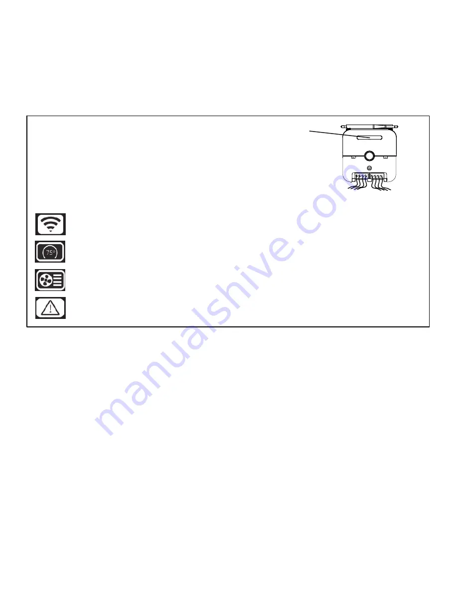
Five indicators are located on the front of the Smart Hub enclosure

(near the top edge). One indicator location is reserved for future expan­

sion and has no icon and no current function. The other four locations

have icons depicting Smart Hub functions and are back-lit by LEDs.

From left to right:

Wi-Fi

 – Indicates the status of the internal Wi-Fi module and whether or not it is connected to the home Wi-Fi

network.

Thermostat – Indicates the status of the thermostat Mag-Mount and HD Display and whether or not the Smart
Hub can communicate with the HD Display.

HVAC – shows the status of the HVAC equipment in the home controlled by this Smart Hub, and whether or
not the Smart Hub can communicate with them.

ALERT 

– shows if there is a critical alert condition.

Smart hub indicator display location

Figure 1. Smart Hub Indicators and Connectors

1.4.2. General Rules

S

Unlit indicators show there is no power to the Smart Hub or its software has suffered a critical initialization
error.

S

Steady amber indicators show Smart Hub boot up and self-check processes are in progress or have com­
pleted. Boot-up and self-checks normally complete rapidly, so amber indicators may appear only briefly
(except for the Wi-Fi indicator).

S

Flashing amber Wi-Fi indicator shows that the Wi-Fi module check is in progress. Steady amber Wi-Fi
indicator shows that the Wi-Fi module has passed its check but is not connected to the home Wi-Fi net­
work.

S

Flashing green indicators show acquisition and test of resources across wired interfaces to the Mag-
Mount / HD Display and to installed HVAC equipment

S

Steady green indicators show that the associated function is connected and operating normally.

S

Flashing red indicators shows a problem with the associated function.

S

Flashing red ALERT indicator shows that a critical alert condition exists. If one of the other indicators is
also flashing red, that is the likely source of the alert. If no other indicators are flashing red, the source
of the alert is not defined.

Содержание 12U67

Страница 1: ... 1 iComfort S30 Smart Thermostat Color Touchscreen Programmable Wi Fi Communicating Thermostat ACC 15 03 September 22 2015 Revised February 23 2016 12U67 CHEAT SHEET TOPICS AND TROUBLESHOOTING TIPS ...

Страница 2: ... 13 4 3 Electrical Discharge 13 4 4 Screen Locks Up or Goes Blank 13 5 Dealer Portal 14 5 1 Spoofing 14 5 2 Remote View and Control 14 6 Creating Consumer Portal Account 14 6 1 Setting Up Account 14 6 2 Adding System to Consumer Account 15 7 Removing System from your Consumer Portal Account 15 7 1 Remove Home 15 7 2 Move Out 15 8 IComfort Mobile Setup Application 16 8 1 Operating System Requiremen...

Страница 3: ...ives 24VAC power from the indoor unit over two wires and communicates with the indoor unit and the rest of the HVAC system through two different wires Wiring from the Smart Hub to the indoor unit should be limited to 300 feet or less for 18 AWG wire 1 3 2 Smart Hub to Mag Mount Terminal Connections Type Smart Hub Terminal Labels Mag Mount Terminal Labels Terminal Color Function RS 485 Yellow Two w...

Страница 4: ...dition Smart hub indicator display location Figure 1 Smart Hub Indicators and Connectors 1 4 2 General Rules S Unlit indicators show there is no power to the Smart Hub or its software has suffered a critical initialization error S Steady amber indicators show Smart Hub boot up and self check processes are in progress or have com pleted Boot up and self checks normally complete rapidly so amber ind...

Страница 5: ...twork connection with an other Smart Hub in the home or with a mobile device running the iComfort S30 service maintenance application S Steady green when the Smart Hub is connected to a mobile device running the iComfort S30 service maintenance application through a Lennox managed local network connection This is considered a transient state because the mobile device will disconnect from the Lenno...

Страница 6: ...D Display Two wire serial RS 485 interface 3 3 V signaling up to 400 feet to Mag Mount 18 AWG wire 1 6 Networking Multiple Smart Hubs Single Smart Hub Group Thermostat software release 3 00 S If more than eight iComfort S30 Smart Thermostat HVAC are needed in a home they can be segregated into groups with each group containing eight or less Smart Hubs n Group 0 is for a stand alone Smart Hub or th...

Страница 7: ... they are spread among several groups 2 Mag Mount 2 1 Mounting to 2x4 Electrical J Box 2 1 1 Short Term Recommendation Use Honeywell back plate from LPP store part X5392 2 1 2 Back plate Long Term We will enlarge the existing back plate to cover 2 x 4 J box and replacement of larger stats with the iComfort S30 2 1 3 Wiring Connections 2 1 3 1 Wire gauge and Maximum Run Length The Smart Hub connect...

Страница 8: ... is the most common issue n There has been a software error in the Mag Mount processor n There has been an internal hardware error in the Mag Mount S Off Possible causes n Mag Mount is not receiving power from the Smart Hub Check wiring at Mag Mount and Smart Hub A mis wiring will not cause any damage but will prevent the system from operating n There has been a serious Mag Mount internal hardware...

Страница 9: ...bleshooting with Display Removed Check for 12VDC on Mag Mount terminals and 2 2 4 HD Display Interface Electrical Do not push on terminals S Ground S 5 VDC S RX S TX S Sense Figure 4 Mag Mount HD Display Contactors ...

Страница 10: ...n the home and enable Smart Away B Go to Menu Settings Away and toggle the smart away button to ON Also set the away set points 3 2 IComfort Thermostat Application A Smart Away can also be enabled using the mobile device iComfort Thermostat application Go to your mobile device and start the iComfort Thermostat application B Go to My homes and select the first system Then select menu settings away ...

Страница 11: ...i B Wi Fi network will show not connected Press on not connected C Select other D The enter new network information screen will appear Enter the name of the hidden network E Select Security Options are none WEP WPA and WPA2 DO NOT USE A GUEST OR UNSECURE ACCESS POINT F Once security type is selected a password field will appear Enter the password and press join to contin ue NOTE If you wish to see...

Страница 12: ... and possibility fix your issue remotely recommended F Check that you agreed to the Lennox EULA Press on LENNOX EULA to read the end user license agree ment If the setup and connection to the Lennox server is successful a green check mark will appear above the service icon under the wi fi menu option 4 1 3 Adding Additional Thermostat to your Consumer Account This information should have already b...

Страница 13: ...lly 4 3 Electrical Discharge Display will indicate error unable to communicate with Smart Hub This pop up will be on the display for 3 minutes which will cause the watchdog to reset the Display after three minutes All will recover fine after the reset This whole process took between 5 6 minutes 4 4 Screen Locks Up or Goes Blank If the HD Display screen freezes or goes blank then perform a reset Re...

Страница 14: ...llow you access to all customers assigned to that dealer You will be able to view and remote into a customer s account just like the dealer can if the homeowner has given permis sion to do so 5 2 Remote View and Control Dealer will only be able to remote view or control dealer control center section and configurable parameters only if Dealer Remote View and Control has been enabled at the homeowne...

Страница 15: ... F Your system should appear momentary on the consumer portal screen 7 Removing System from your Consumer Portal Account A system can be removed using either the Consumer Portal or directly from the HD Display There are two methods that are available to remove the system either remove home or move out NOTE If you have given your dealer remote in access they will no longer be able to remotely acces...

Страница 16: ... eight digits of the Smart Hub SSID as the password example E3005200 F Once connected to the mobile device the Smart Hub center ring LED turns solid green G Start the iComfort Mobile Setup Application and make sure you connect to the correct Smart hub by checking the serial number NOTE The serial number check is only needed if multiple Smart Hubs are shown For example if you have three systems and...

Страница 17: ...he Smart Hub will auto disconnect from the mobile device Repeat procedures to reconnect 8 3 Connecting iComfort Mobile Setup Application to Smart Hub using Smart Hub Wi Fi alternative method From the home screen go to menu settings advanced settings pair Smart Hub to iComfort dealer commis sioning app selection It will auto connect to iComfort Mobile Setup Application and start you at the dealer c...

Страница 18: ... to your mobile device s owners manual on how to use your Wi Fi Connection tool E To connect to the Smart Hub use the last eight digits of the Smart Hub SSID as the password E3005200 F Once connected to the mobile device the Smart Hub center ring LED turns solid green G Start the iComfort Mobile Setup Application and make sure you connected to the correct Smart hub by checking the serial number an...

Страница 19: ... not detect the Smart Hub Short Term Fix Turn off Wi Fi in the thermostat Once the thermostat Wi Fi is disabled the iComfort Mobile Setup Application will be able to detect the Smart Hub and connect to it Go to thermostat home screen and touch the menu icon Touch settings and then wi fi to access the Wi Fi setting screen Toggle the option to OFF NOTE Remember to turn on the thermostat Wi Fi once s...

Страница 20: ...urn your mobile data setting back on when you are finished with the Lennox Mobile Setup application 2 Mag Mount Front Cover and HD Display Issue When mag mount is powered and the HD Display is not attached there is a bright blue LED that can be seen on the front If it is solid blue then you have voltage It also indicates the mag mount is communicating with the smart hub If the blue LED is blinking...

Страница 21: ...on and is flush with the case PROXIMITY SENSOR RESET BUTTON SPEAKER FOR FUTURE USE FOR FUTURE USE 4 Mag Mount Mounting Screw and HD Display Issue There has been a few instances were the Mag Mount screw used to secure the device to the wall at the 6 O clock position pushes the Mag Mount out enough to sever the electrical communication connection between the HD Display and Mag Mount Solution Remove ...

Отзывы: