background image


19 

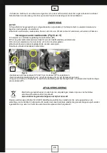
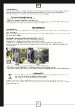
-  If the tine chisel or flat chisel is used at the position of “rotation hammering”, the tool can start to rotate, resulting 

in unexpected accidents. Make sure that they are used at the position of “hammering”. 

(1) Switching to “hammering” 

Turn the function knob counterclockwise. Align 

 of the function knob and  


of the cover as showed in Fig. 7. 

(2) When fixing working positions of flat chisel such as cold chisel, etc.: 

(a) Turn the function knob, Align 

 of the function knob and 


of the cover as illustrated in Fig. 8. 

(b) Turn the selector as illustrated in Fig. 9 and fix the flat chisel to the desired working direction. 
(c) Switch the selector lever to “hammering” according to the procedures mentioned in the above item (1) and 
secure the position of the tool. 
 
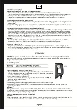
4. Warming up (Fig.10) 

The grease lubrication system in this unit may require warming up in cold regions. 

Position the end of the bit to make contact with the concrete, turn on the switch and perform the warming up 
operation. Make sure that a hitting sound is produced and then use the unit. 

CAUTION: 
When the warming up operation is performed, hold the side handle and the main body securely with both hands to 
maintain a secure grip and be careful not to twist your body by the jammed drill bit. 


MAINTENANCE AND INSPECTION 

 
1. Inspecting the tool 

Since use of a dull tool will degrade efficiency and cause possible motor malfunction, sharpen or replace the tool 

as soon as abrasion is noted. 

2. Inspecting the mounting screws 

Regularly inspect all mounting screws and ensure that they are properly tightened. Should any of the screws be 
loose, retighten them immediately. Failure to do so could result in serious hazard. 

3. Maintenance of the motor 
    The motor unit winding is the very “heart” of the power tool. Exercise due care to ensure the winding does not 

become damaged and/or wet with oil or water. 

4. Inspecting the carbon brushes  
   The Motor employs carbon brushes which are consumable parts. When they become worn to or near the “wear 
   limit”, it could result in motor trouble. The red service indicator LED lights up when the carbon brushes are worn 
   out to indicate that the tool needs servicing.


The power tool must then be sent to an after-sales service agent. 

When you have to replacement the carbon brushes by yourself, please following the order

: 

(1)  Loosen the four set screws and remove the fan cover.  
(2)  Remove the helical spring and carbon brushes.  
(3)  After replacing the carbon brushes, install the helical spring and fan cover, with securely tightening four set 

screws.


CAUTION: 
Repair, modification and inspection must be must be carried out by a LEMAN Authorized Service Center. 
In the operation and maintenance of power tools, the safety regulations and standards prescribed in each country 
must be observed. 
 
MODIFICATIONS: 
LEMAN Power Tools are constantly being improved and modified to incorporate the latest technological 
advancements. 
Accordingly, some parts (i.e. code numbers and/or design) may be changed without prior notice. 


DISPOSAL 

 
                   Do not dispose of electric tools together with household waste material! 

In observance of European Directive on waste electrical and electronic equipment and its 
implementation in accordance with national law, electric tools that have reached the end of their life 
must be collected separately and returned to an environmentally compatible recycling facility. 


GB 

Содержание PSM040

Страница 1: ...MOD LE MODEL MODEL MODELO PSM040 Manuel d utilisation Instruction manual Gebruiksaanwijzing Manual de instrucciones 07 08 2015...

Страница 2: ...pe Type Tipo Hand held hammer drill Boorhamer Martillo Rotativo Mod le Model P40 N de s rie Serial number 2015 Marque Brand LEMAN R f rence Reference PSM040 Est en conformit avec les normes ou directi...

Страница 3: ...rtelage Cette machine r pond aux attentes des amateurs avertis et des professionnels Dans le but d am liorer nos produits nous restons l coute de vos remarques et critiques n h sitez pas nous en faire...

Страница 4: ...4 Fig 1 Fig 2 Fig 9 Fig 10 Fig 7 Fig 8 Fig 3 Fig 4 Fig 5 Fig 6...

Страница 5: ...P 14 9 R parations P 14 10 Accessoires P 14 11 Liste des pi ces d tach es et vue clat e P 32 12 Certificat de garantie P 37 1 Vue g n rale et pr sentation de la machine avec fournitures standards 3 Pr...

Страница 6: ...ptif des instructions Ces instructions d utilisation vont vous permettre d utiliser votre appareil rapidement et en toute s curit Lisez l int gralit de ces instructions d utilisation avant la mise en...

Страница 7: ...ion et fr quence du secteur correspondant celles mentionn es sur la plaque signal tique de la machine protection par un disjoncteur diff rentiel prises de courant correctement install es et contr l es...

Страница 8: ...oute ce que la machine soit en bon tat v rifiez que les dispositifs de s curit et de protection fonctionnent parfaitement v rifiez que les pi ces mobiles fonctionnent correctement et ne se bloquent pa...

Страница 9: ...s e pendant l usinage Utilisez les outils appropri s pour fixer la pi ce usiner N approchez jamais les doigts les mains ou les bras de l outil en fonctionnement Ne portez ni bague ni bracelet ni tout...

Страница 10: ...ecteur pendant toute la dur e de ces op rations veillez ce qu elle soit d branch e 5 1 Montage de la poign e lat rale auxiliaire La poign e lat rale auxiliaire 7 doit imp rativement tre utilis e lors...

Страница 11: ...riorer la machine le r glage doit se faire machine l arr t Attention Ne forcez jamais sur le s lecteur faites tourner le mandrin manuellement si le s lecteur ne se met pas en position facilement 6 2...

Страница 12: ...correctement install es et contr l es Placez le c ble lectrique de fa on ce qu il ne vous g ne pas pendant votre travail et ne puisse pas tre endommag Prot gez le c ble lectrique de tout facteur susc...

Страница 13: ...Ne remplacez les pi ces d t rior es que par des pi ces d origine contr l es et agr es par le constructeur L utilisation de pi ces non contr l es ou non agr es peut provoquer des accidents ou des domm...

Страница 14: ...d alimentation lectrique de la machine du secteur La machine ne doit en aucun cas tre sous tension Cette machine est quip e de charbons auto rupteurs qui vont arr ter la machine avant qu ils ne soien...

Страница 15: ...drilling capacity with drill bit 18 30 mm Max drilling capacity with core bit 105 mm Protection class II Overall dimensions LxWxH 480 x 270 x 108 mm Net weight including the auxiliary handle and the p...

Страница 16: ...ng up or carrying the tool Carrying power tools with your finger on the switch or plugging in power tools that have the switch on invites accidents d Remove any adjusting key or wrench before turning...

Страница 17: ...the power tool with a damaged cord Do not touch the damaged cord and pull the plug from the outlet when the cord is damaged while working Damaged cords increase the risk of an electric shock Warning R...

Страница 18: ...Indicator LEDS Fig 4 The green power ON indicator LED lights up when the tool is plugged If indicator led does not light up the mains cord or the controller may be detective The red service indicator...

Страница 19: ...be loose retighten them immediately Failure to do so could result in serious hazard 3 Maintenance of the motor The motor unit winding is the very heart of the power tool Exercise due care to ensure t...

Страница 20: ...uid De typisch A gewogen geluidsniveaus conform EN 60745 Geluidsdrukniveau klopboren in beton LpA 92 24 dB A Geluidsvermogenniveau klopboren in beton LwA 103 24 dB A Geluidsdrukniveau beitelen LpA 93...

Страница 21: ...t de buurt van hitte olie scherpe randen en bewegende gereedschapdelen Beschadigde of in de war geraakte kabels vergroten het risico van een elektri sche schok 5 Wanneer u buitenshuis met elektrisch g...

Страница 22: ...oren inzetgereedschappen en dergelijke volgens deze aanwijzingen Let daarbij op de arbeidsomstandigheden en de uit te voeren werkzaamheden Het gebruik van elektrische gereedschappen voor andere dan de...

Страница 23: ...de machine tot het automatisch wordt vergrendeld Verwijder het gereedschap als deze niet in de machine gestoken kan worden Trek de vergrendelingshuls 4 een paar keer naar achteren Steek het gereedsch...

Страница 24: ...groene voedingsindicatielampje 9 gaat branden als de stekker in het stopcontact is gestoken Als het indicatielampje niet brandt kan het netsnoer of de regeleenheid defect zijn Als het indicatielampje...

Страница 25: ...rs glijden 4 Beide koolborstels dienen tegelijkertijd te worden vervangen 5 Gebruik uitsluitend identieke koolborstels Fig 16 Fig 17 Gebruik een schroevendraaier ST4 2x16 om de deksel 17 te verwijdere...

Страница 26: ...A ponderado t pico determinado de acuerdo con la norma EN 60745 Nivel de presi n sonora taladrado con percusi n en cemento LpA 92 24 dB A Nivel de potencia sonora taladrado con percusi n en cemento L...

Страница 27: ...s a las respectivas tomas de corriente reducen el riesgo de una descarga el ctrica 2 Evite que su cuerpo toque partes conectadas a tierra como tuber as radiadores cocinas y refrigeradores El riesgo a...

Страница 28: ...xisten partes rotas o deterioradas que pudieran afectar al funcionamiento de la herramienta el ctrica Haga reparar estas piezas defectuosas antes de volver a utilizar la herramienta el ctrica Muchos d...

Страница 29: ...dola hacia la derecha Instalaci n o extracci n de la broca Fig 1 Limpie el eje de la broca 2 y apl quele grasa antes de instalar la broca Inserte la broca 1 en la herramienta Gire la broca y presi nel...

Страница 30: ...mpre que el gatillo interruptor 14 se acciona debidamente y que vuelve a la posici n OFF cuando lo suelta Para comenzar a utilizar la herramienta simplemente presione el gatillo Interruptor 14 Su ltel...

Страница 31: ...escobillas de carb n Fig 16 y 17 1 Extraiga y compruebe las escobillas de carb n 81 regularmente 2 Reempl celas cuando se hayan gastado hasta la marca de l mite 3 Mantenga las escobillas de carb n lim...

Страница 32: ...8 Pivot de ressort Spring pole 1 19 S lecteur de fonction Function knob 1 20 Vis cruciforme ST4 2x16 Tapping screw ST4 2x16 14 21 Circlips 42 Retaining ring 42 1 22 Bague d tanch it 30x 42x3 Woolen ri...

Страница 33: ...73 Vis cruciforme ST4 8x58 Tapping screw ST4 8x58 2 74 Rondelle plate 5 Flat washer 5 2 75 Stator Stator 1 76 Rotor Armature 1 77 Aimant Magnetism inductorium 1 78 Roulement billes NMB 608D Ball bear...

Страница 34: ...04 Vis sp ciale Abnormity bolt 1 105 Support de poign e lat rale Side handle assembly base 1 106 Vis papillon Papilionaceous bolt 1 107 But e de profondeur Orientation staff gauge 1 108 Ecrou M6 Nut M...

Страница 35: ...35 Figure A 2015 08...

Страница 36: ...36 Notes...

Страница 37: ...pour effet de proroger sa date de validit Les r parations ne donnent lieu aucune garantie Les r parations au titre de la garantie ne peuvent tre effectu es que dans les ateliers de votre revendeur ou...

Страница 38: ...38 Notes...

Страница 39: ...39 Notes...

Страница 40: ...40 Z A DU COQUILLA B P 147 SAINT CLAIR DE LA TOUR 38354 LA TOUR DU PIN cedex FRANCE T l 04 74 83 55 70 SAV 04 74 83 69 88 Fax 04 74 83 09 51 info leman sa com sav leman sa com www leman sa com...

Отзывы: