background image


Version 2.1 
09/2010 

NOVOLAS Basic AT 


Operation 


43 


Register 

Index 

Name 

Function 

Units 

Value range 

103 

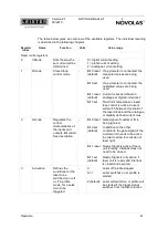
I_s 

Actual current 
emitted by the 
current source 

0.1A  0-4095, current capability depends on 

current source module.  
With the Air Cooled Laser Module, the unit is 
0.01A) 

109 

T_Pyro 

Measured 
temperature value 
of pyrometer 

The unit depends on the value of bit 0 in 
register 1. If this bit is set, the value is the 
equivalent temperature of a blackbody 
multiplied by 10. If this bit is not set, the raw 
pyrometer measurements are displayed. 

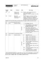
Register 120: The function of the values depends on the type of current source that is used. 

120 

Current Source (Standard Version) 

120 

Error 

Actual error value 


0:   NO ERROR: No Error 

1:  LUMV_MISSING: Current source is 

connected but 5V output is below 
threshold current value. 


B

it

 c

o

d

e

d


2:  GATE SIGNAL TIMEOUT: The 

activation-signal (typically from CIO) 
has not been repeated quickly enough 
during the activation phase. 
Communication problem between CIO 
and Laser module? 

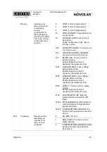
120 

Current Source: air cooled laser module 

120 

Error 

Actual error value 


NO ERR: no error 

TEMP_1: Error Temperature 1 

TEMP_2: Error Temperature 2 

TEMP_3: Error Temperature 3 

TEMP_4: Error Temperature 4 

16 

CONTROLTEMP: Temperature Error 
in Laser diode 

32 

CURRENT LIMIT: Current error in 
laser diode. 
Check configuration. Take note of the 
max current. 

128 

CURRENTSOURCE: Common error 
in current source 


B

it

 c

o

d

e

d


256 

CURRENTSOURCE_VERSION: 
wrong version of current source. 


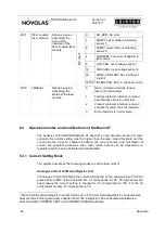
 Wenn bei bitcodierten Registern ein Wert steht, der nicht in der Liste aufgeführt ist, bedeutet dies, 

dass mehrere Fehler gemeinsam auftreten. Wert 160 in Register 120 beudeutet beispielsweise, 
dass die Fehler CURRENT LIMIT und CURRENTSOURCE auftreten. 

Содержание NOVOLAS Basic AT

Страница 1: ...System Manual NOVOLAS Basic AT Version 2 1 09 2010 Subject to change without notice Änderungen vorbehalten ...

Страница 2: ...6 152 fax 49 241 8906 558 e mail info leister technologies de http www leister technologies de Leister Technologies Ltd Building A 1588 Zhuanxing Road Shanghai 201 108 PRC phone 86 21 6442 2398 fax 86 21 6442 2338 e mail leister leister cn http www leister cn Leister reserves the right to update the content of this manual at any time without prior notification Copyright This document may not be co...

Страница 3: ...k To Laser Module X81 27 4 4 3 Cooling Supply To External Laser Modules 27 5 Installation 28 5 1 Important notices 28 5 2 Transportation 28 5 2 1 Local transportation 28 5 2 2 Long distance transportation 29 5 2 3 Transport damage 29 5 2 4 Packaging materials 29 5 3 Location 29 5 4 Conditions for setting up 30 5 5 Installation instructions 30 5 5 1 Time scheme for typical Integration 37 5 5 2 Typi...

Страница 4: ...ound in chapter 9 of this manual Checklists for installation found in Chapter 5 5 for maintenance in chapter Maintenance of this Manual 1 2 Specialist personnel This manual with the following stipulations is addressed to specialist personnel Transportation Personnel with the relevant knowledge Installation End user having read and understood this manual Wartung End user having read and understood ...

Страница 5: ...resulting damages and the risk lies solely with the user The materials and components processed as well as the parameters set are to be selected such that no emissions vapors smoke etc arise during proper use of the system If this cannot be avoided care must be taken that the emissions arising are completely extracted and filtered observe the relevant regulations The NOVOLAS Basic AT system must n...

Страница 6: ...Basic AT without prior consultation and written approval from Leister Process Technologies The safety of the NOVOLAS Basic AT is compromised at best as a result of modifications The user is exclusively liable for all damages arising from alterations which are not expressly approved by Leister Process Technologies Replacement parts must conform to Leister Process Technologies specified technical re...

Страница 7: ...ent of the entire equipment Pay special attention to the hazards arising from the NOVOLAS Basic AT itself as described in this manual The NOVOLAS Basic AT should particularly only be put into operation if The accessibility to the laser radiation has been prevented beyond the limit value of Laser Safety Class 2M protective guards protection of the danger zone etc see EN60825 1 The NOVOLAS Basic AT ...

Страница 8: ...iation is partly invisible and can cause irreparable damage to the eye or skin warning labels see chapter 9 It is the responsibility of the system integrator to integrate the system such that no hazardous laser radiation escapes from any part of the equipment The entire equipment must at least conform to Laser Class 2M in accordance with EN 60825 1 2007 2 2 Safety of the NOVOLAS Basic AT system On...

Страница 9: ...c AT into operation without having connected the optical fiber at both ends Laser module and processing optics Wear EN207 208 compliant laser protection goggles eye protection for laser radiation when you disable the laser protection devices for repair work The most important protective measures when dealing with laser radiation are contained in the standard EN60825 1 Radiation safety of laser pro...

Страница 10: ...permanently damage your eyes Implement the necessary protective measures in the danger zone of the NOVOLAS Basic AT in order to avoid exposure of eyes or skin from direct or scattered radiation and to warn of hazards also see the standard EN60825 1 Observe the statutory and local laws regulations governing the operation of laser products Laser Class 2M The aiming laser which is installed in the NO...

Страница 11: ...duct hazardous voltage Touching live parts can be fatal Be aware that the overvoltage protection Z1 and the filter Z2 are always connected to mains even when main switch is off Fuses F1 F4 may only be exchanged when mains switch is off because both contacts carry live hazard voltages Work on electrical equipment or operating materials may only be carried out by electricians or from trained personn...

Страница 12: ...he operating company to correctly connect the mains cable and to ensure a continuous earth connection 2 2 3 Hazards from gases or vapours When processing certain materials using the NOVOLAS Basic AT toxic or non toxic gases and or fumes can be emitted as a by product Please contact your material supplier Ensure complete extraction and filtration of the gases vapours produced The gases vapours can ...

Страница 13: ...s check may be configured differntly according to the requirements of the customer 2 3 2 Laser enable key switch internal The laser enable key switch must be activated in order to operate the laser modules Disabling the key switch will disconnect the current sources from the mains supply and block the laser safety switches 2 3 3 Emergency stop button internal and external See chapter 4 2 1 for con...

Страница 14: ...bined to build a customized laser systems optimized for plastic welding applications The figure below represents the structure of the NOVOLAS Basic AT NOVOLAS BASIC AT Control Unit Novolas Basic AT Customer I O A System Master AT Customer I O m Cooler AT Laser unit n Optics Head Cabezal óptico Current Source Laser Module Laser unit A fiber coupled Optics Head Current Source Laser Module Figure 2 S...

Страница 15: ...nebeam Current Source Linebeam Laser module Optics Figure 3 Systematic Outline of system configuration featuring at least one linebeam NOVOLAS BASIC AT Control Unit Novolas Basic AT Customer I O A System Master AT Customer I O m Laser unit n air cooled Módulo laser systema de refigeración Fuente de alimentación Cabezal optico Laser unit A air cooled Laser module Cooling System Current Source Optic...

Страница 16: ...ttached optics head The surrounding modules support the operation of the laser unit The central cooler assures the cooling of the laser diodes The Customer I O builds the interface to the surrounding customer specific environment The System Master is responsible for the configuration and integrity checks during setup and the surveillance of the system during operation The NOVOLAS Basic AT control ...

Страница 17: ...m can only be reset by powering down and up the whole system Each individual laser unit module has additional states Laser Unit Not Started Laser Unit Initializing Laser Unit Ready Laser Unit Ready Inactive Laser Unit Ready Active Laser Unit Error The Laser Unit Ready state will persists until the reset button is pressed and therefore the current sources are powered up The laser unit enters then L...

Страница 18: ...terfaces to start the system stop the system Emergency Stop unblock the interlock of the laser modules set laser module current activate the laser diodes monitor system state These interfaces are provided on terminal blocks X90 X94 and on connectors of the Customer I O module Figure 6 Connecting Array of NOVOLAS Basic AT ...

Страница 19: ...These contacts are in parallel to the blue push button on the front of the NOVOLAS Basic AT After main power on shorting these two contacts for more than 100 ms will enable the power supply of the laser diode and start the cooling system depending on factory setting the cooler might start immediately after main power is applied X90 3 Emergency Stop channel A X90 4 Emergency Stop channel A These te...

Страница 20: ... X94 4 IL Channel A The individual laser module can only be enabled if both interlock circuits are closed simultaneously Only dry contacts are allowed Be aware that the terminals are not consecutive numbered Delays during opening or closing the contacts of the two channels of more than 100 ms will cause a module error Shortage between the two circuits will be detected If one of the channels is ele...

Страница 21: ...be supplied by the customer on terminal 14 1 Voltages higher than 14V are considered logic high Terminal Description Potential Trigger Info DataManager X14 1 External digital IO supply and signal GND connected to X15 1 Reference potential X14 2 Aiming laser off 24V lasers off Bit 7 X14 3 res not used Bit 6 X14 4 res not used Bit 5 X14 5 res not used Bit 4 X14 6 Trigger laser unit B D 24V active Bi...

Страница 22: ...Unit B D on Bit 4 X15 6 Laser Unit B D ready Bit 3 X15 7 Laser Unit A C error or not ready Bit 2 X15 8 Laser Unit A C on Bit 1 X15 9 Laser Unit A C ready Bit 0 X15 10 External digital IO supply connected to X15 10 24V At power up the signals X15 3 System error or not ready and X15 7 X15 4 Laser unit X error or not ready are active As soon as the system inizializes and enters System ready state the...

Страница 23: ...uperior unit will then evaluate the signals on X15 4 and X15 5 and complete the welding cycle Terminal Description Potential Trigger Info DataManager X15 1 External digital IO supply and signal GND connected to X14 1 Reference potential X15 2 Interlock states Bit 7 X15 3 System error or not ready Bit 6 X15 4 Good Bad Evaluation Part not good Bit 5 X15 5 Good Bad Evaluation Part good Bit 4 X15 6 Go...

Страница 24: ...it A C optional X16 4 Current preset laser unit B D usually 1V per 10A X16 5 Current preset laser unit A C usually 1V per 10A 4 3 5 Analogue Outputs X17 General specification Voltage range 0 to 10 Volt Impedance app 10 kOhm Max Output current 1mA Attention Common reference potential with analogue inputs and serial ports Terminal Beschreibung Potential X17 1 Signal Common GND X17 2 Pyrometer signal...

Страница 25: ... PC Sub D 9 Pin 5 X18 2 RX RS232 Input must be connected to the TX of a RS232 interface e g PC Sub D 9 Pin 3 5V X18 3 General Input 5V X18 4 TX RS232 Output must be connected to the RX of a RS232 interface e g PC Sub D 9 Pin 2 5V X18 5 General Output 5V 4 3 7 Serial Interface RS422 X36 General specification connection and application settings depends on the installed software Attention Common refe...

Страница 26: ...l laser modules directly connect to this interface It must no be used to connect other equipment 4 4 1 High Current Connector X 80 X80 The high current connector delivers the operating current to external laser modules For currents up to 75 Amps one connector for each polarity is provided For currents up to 150 Amps two connectors for each polarity are provided and the current is shared between th...

Страница 27: ... Built in connector type 4 contacts female connector Binder Series 712 Counterpart 4 contacts male connector EMI protected Binder Series 712 Art Nr 99 0409 10 04 4 4 3 Cooling Supply To External Laser Modules The cooling circuit of the external laser module must be connected here Adapter flow line Incorporated type Legris Art Nr PLCD 1600412 Counterpart Legris Art Nr PLCD 2300412 Adapter return li...

Страница 28: ...o a separate power supply fused by a line safety switch rated 16A The protective earth connecter must be connected to the earth potential Caution invisible laser radiation Direct or scattered radiation can lead to irreversible damage to eyes or skin 5 2 Transportation 5 2 1 Local transportation Local transportation is defined as moving the NOVOLAS Basic AT within a building Temperatures above 0 C ...

Страница 29: ...adius of the fiber Fit the protective caps on all fiber optic cable connectors the laser module and the optic modules Lift the NOVOLAS Basic AT on a pallet or the base of the transport box 5 2 3 Transport damage Check the NOVOLAS Basic AT for damage prior to unpacking Should you discover any damage notify the following immediately Transportation company Transportation insurance Leister Process Tec...

Страница 30: ...ifications for environmental conditions Setting up connection and operation of the NOVOLAS Basic AT must be in agreement with your relevant safety regulations The owner is solely responsible for compliance with safety regulations Minimum distance to walls or other machines 5 cm to the underside of the housing 20 cm to top of the housing 50 cm on the front and the rear of the system Service is easi...

Страница 31: ...rsion 2 1 09 2010 NOVOLAS Basic AT Installation 31 System Master AT Laser Module Chiller Customer I O AT Fiber connector Exhaust Air Figure 10 Basic AT Side View Figure 9 NOVOLAS Basic AT System Overview ...

Страница 32: ...onnection and overvoltage protection Netzanschluss und Überspannungsschutz Fuses F1 F4 Sicherungen 24V Supply 24V Versorgung Ethernet Switch Safety Relays Sicherheitsrelais System Master AT Customer I O AT Terminals X90 X91 etc Figure 11 Basic AT View into control slot ...

Страница 33: ... Fiber optic cables must be protected against mechanical stress Prepare AC power connection see 0 1 2 Unpack and check for transportation damage Store ship back packaging materials 1 3 Place the NOVOLAS Basic AT in desired location Open the upper cover plate and back plates to access connection zones If possible also open right side panel 5 3 0 Step Cooling system Remarks 2 1 Fill cooling system w...

Страница 34: ...st be installed Always use both channels and do not short the channels 4 2 2 Do not bridge Never operate the NOVOLAS Basic AT system with defeated interlock 3 5 In default mode the gate and the trigger signal must be connected to the Customer I O s digital inputs supplied by an external 24V supply The current will be set by an analogue voltage on the analogue inputs of the Customer I O 6 3 Dependi...

Страница 35: ...d 5 4 For optics equipped with pyrometer Connect the optic via CAT5 Ethernet cable to the POE Injector in the Basic AT See Figure 12 of control rack 5 5 Option Globo optics Connect air supply for ball bearing and clamping device Adjust focus position 5 6 Option Line beam lasers Connect water pipes and power cable to line beam laser head If equipped with pyrometer Connect the optic via CAT5 Etherne...

Страница 36: ...nal 1 and 2 must be 230V 10 50 60Hz The diameter of the cables must be min 2 5 mm The litz wires have to be fixed by means of a cable binder in a min distance to the terminals Mains supply must be protected by a 16A fuse and a continuous ground connection Use fuses with slow tripping characteristic or high surge current capability since the switching power supplies require high inrush current 6 2 ...

Страница 37: ...nal active Keyswitch Enable 5 Trigger Status change System running Interlock Input Interlock Test Internal Gate CIO Input Trigger CIO Input Analog In CIO Input Laser Current Ready Signal CIO Output closed open on off Active Inactive 10 V 0 V 100 A 0 A tin 100 ms 150 A for Linebeam Active Inactive Active Inactive Laser ON Laser Off as Interlock is open start up phase Laser ON Figure 14 Signal Schem...

Страница 38: ...10 X16 1 X16 5 Output X90 7 X90 8 X90 9 X15 1 X15 7 X15 8 X15 9 X15 10 X80 X80 X81 EI Start Reset close min 100ms to start system Emergency Stop open to stop operation Interlock close for lasing Ext 24V Power supply Laser on off close to switch on laser Internal connection U Set laser current 1V 15A 24V 0V AT Electrical Interface Warning laser system powered redundant Laser unit ready Laser on Las...

Страница 39: ...configuration file in case modules are being replaced Please contact a Leister service representative for support After this all Basic AT laser modules will be initialized and wait until the temperatures of the laser modules are below their maximum cooling temperatures usually 21 C After all the modules have been ini tialized the system is ready for operation This is indicated by active signals on...

Страница 40: ...pted by sending an ASCII 8 BS character The system would acknowledge this by sending BRK CR LF Reading and writing of parameters Parameter read rX CR LF Parameter write wX Y CR LF X stands for the register index no and Y stands for the register value Be aware that there is no blank character between the command character and the register index The register value X is separated by a blank character...

Страница 41: ...ill switch between threshold of the laser diode and the analogue or digitally defined current max Bit 0 reset Gate signal of customer IO is being ignored Bit 0 set default In addition to the other conditions the gate signal of the customer IO needs to be active in order to allow for emission of laser light Bit 1 reset Ready Signal is active if laser unit is ready Interlock does not need to be clos...

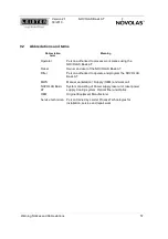
Страница 42: ...f an interval in profil mode 1 ms 0 60000 16 Register P_TO P_T15 Register Index Name Function Units Value range 900 Guiding Laser If a 1 is written the pilot laser will be switched on Note if the Input Guidung laser off is activated on the Customer IO the guiding laser will stay inactive 1 default guiding laser will be on else guiding laser will be switched off 999 Store Parameters If a 1 is writt...

Страница 43: ...but 5V output is below threshold current value Bit coded 2 GATE SIGNAL TIMEOUT The activation signal typically from CIO has not been repeated quickly enough during the activation phase Communication problem between CIO and Laser module 120 Current Source air cooled laser module 120 Error Actual error value 0 NO ERR no error 1 TEMP_1 Error Temperature 1 2 TEMP_2 Error Temperature 2 4 TEMP_3 Error T...

Страница 44: ...nication with CustomerIO failed 16384 OPTICINTERFACE_LINK Ethernet communication with OpticInterface pyrometer failed 32786 ILOPENEDWHENLASERON The interlock was opened when the laser was on Register Index Name Function Units Value range 0 Off Current source is off 1 ReadyInactive Current source delivers no current 2 ReadyTestCurrent Current source is activated and delivers the test current 3 Read...

Страница 45: ...SERVOLTMIN Laser voltage dropped below minimum Restart Replace module if necessary bei Leister service 4096 SAFETY Common error in safety module Restart Replace module if necessary bei Leister service 8192 CUSTOMERIO LINK Ethernet communication with CustomerIO failed 16384 OPTICINTERFACE_LINK Ethernet communication with OpticInterface pyrometer failed Module interlock error when using an air coole...

Страница 46: ...asic AT The behavior of the NOVOLAS Basic AT depends on the operation mode For laser emission the current setting must be higher than the laser diode threshold and the current source must be enabled Enabling the current source and calculation of current are separate processes Also laser diode current can be dependent on regulators which can be activated and deactivated 6 3 1 Current Setting Mode T...

Страница 47: ...odule in units of 0 01A into the registers 8 10 12 Also the durations Unit ms have to be written into the registers 9 11 13 Once a profile is started the system will generate a current profile starting at the first current value interpolation point Register 8 and will then linearly interpolate to the next interpolation current value Register 10 within the specified duration Register 9 The followin...

Страница 48: ... If the trigger input on the Customer I O is inactive current is 0 Profile Mode Register 3 value Function From 0 to 1 Profile is started Profile ends if the value is 0 2 A profile is started if the trigger input on the Customer I O is transiting from inactive to active Profile ends if the Trigger input is deactivated 6 3 3 On Off Temperature Regulator Register 1 and 6 If the system is equipped wit...

Страница 49: ...rror state and can only be restarted by a power down and up cycle If one of the laser units registers an error the appropriate error signal on the Customer I O is set and the laser units remains in Error state until the temperature reaches an acceptable level again Interlock monitoring The interlock circuit is tested every time the interlock is closed by the operator Each function is tested by sof...

Страница 50: ... g laser module waits for sufficient cooling Green blinking Initialized Environmental conditions are met Module is ready for start Green Run Module is in working state Red blinking Shut down Module has been shut down Red Error Module has encountered an error E g cooling not sufficient overheating low flow rate overcurrent 2x Green 1x Red Reset Module is in Reset State 6 6 2 Diagnostic Lamp L2 L2 s...

Страница 51: ...oes not behave as intended If your problem already occurs during commissioning please carefully check both the Installation Instructions in Chapter 5 5 and the configuration of the system as described in 6 2 If this manual does not help you solve the problem please plug an empty PC formatted USB memory stick into the USB interface on the front side of the NOVOLAS Basic AT and leave it plugged in f...

Страница 52: ... Refill pure DI water For instructions see Module Manual Cooler AT Cooler Water flow To low water flow rate Check cooling circuit Replace water filter cartridge If this error occurs more frequently than every 6 months please contact Leister service personal System does not start up System error or not ready signal of Customer I O always active Power supply System Master defect Ethernet connections...

Страница 53: ... gate or trigger signal Check current setting Replace laser module Weak laser power Dirty optics Fiber optic not tightly connected to Laser module or optical housing Damaged laser module Check optics and clean if necessary Check fiber optic connector on laser module and optical housing Replace laser module 7 4 Optics fault Error Cause Measures Bad aiming beam or bad welding result Dirt on Optics B...

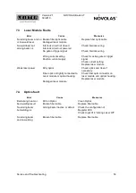
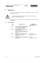
Страница 54: ...e intervals Interval Maintenance work NECESSARY REPLACEMENT PARTS 1 month Close visual inspection of exit lens for dirt or coating Carefully unscrew lens if necessary and clean it None 3 months Calibration of diode laser unit with laser power meter Must be done by person trained in servicing lasers Not described in this manual None 6 months Replace the particulate filter of the laser cooler unit W...

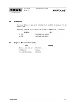
Страница 55: ... Leister Process Technologies Standard small parts such as screws etc can also be obtained from other sources Article No Part 131 601 Particulate filter element 120 799 De ionization cartridge 8 3 Disposal of replacement parts Part Disposal Particulate filter element Waste bin Cooling water Sewage De ionization cartridge Waste bin ...

Страница 56: ...m direct or scattered radiation and to warn of hazards also see the standard EN60825 1 This symbol warns of dangerous electrical voltages Shut down the NOVOLAS Basic AT system before commencing repair work protect against unauthorized operation and disconnect the NOVOLAS Basic AT systems mains plug Check whether parts which could be live during operation are live This symbol warns of Electrostatic...

Страница 57: ...er and user of the NOVOLAS Basic AT Fitter Person authorized to operate and program the NOVOLAS Basic AT MWS Manual workstation Supply OEM and work cell NOVOLAS Basic AT System consisting of Power supply laser unit laser power supply Cooling system Optical fiber and Optics OEM Original Equipment Manufacturer Service technician Person trained by Leister Process Technologies for installation service...

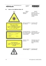
Страница 58: ...s and optic modules Warning of hazardous laser radiation On the rear of the system housing Label with data of the laser radiation emitted from the diode laser and aiming laser On the rear of the system housing on the laser heads and laser modules Indication of laser beam exit At the laser beam exits on the laser module laser optics and laser heads Warning of hazardous electrical voltage On the rea...

Страница 59: ...he housing Laser system Type NOVOLAS Basic AT Article Nr 127 357 RM SN Laser unit A Laser unit B Laser unit C Laser unit D 230 VAC 10 50 60 Hz 16 A 3600 W Made in Switzerland LEISTER Process Technologies CH 6060 Sarnen Service contact tcs laser leister com TYPE LABEL Typenschild On the rear of the system housing Auf der Rückseite des Gehäuses ...

Страница 60: ...d 3 m wires 2 5 mm2 10 2 Dimensions and weight Dimensions width x length x height Height can be increased in 4HE steps up to 25HE 550 mm x 780 mm x ca 700 mm 12HE Version 550 mm x 780 mm x ca 878 mm 16HE Version 550 mm x 780 mm x ca 1056 mm 20HE Version 550 mm x 780 mm x ca 1234mm 25HE Version Distance to Front and Rear Min 50 cm Distance to top and underside Min 20cm top 5 cm underside Weight app...

Страница 61: ...iode laser power Fiber coupled lasers max 400 W cw at aperture of each laser module Aiming laser power max 5 mW cw at aperture of each laser module Type of operation controlled current operation Min bending radius of fiber Min 200 mm for SMA fiber Min 250 mm for HiYAG fiber 10 5 Liquid Cooling System Cooling medium de ionized water conductivity 5 10 µS filtered 20 µm Capacity approx 3 5 liter tota...

Страница 62: ...NOVOLAS Basic AT Version 2 1 09 2010 62 Notes 11 Notes ...

Отзывы: