


SRC Quick Setup Guide
6
SRC_QSG_A1_4.0.10
255-80-0063-00 RoHS
You can connect only one or both inlets to proper power sources.
1. Connect each SRC to an appropriately rated branch circuit.
Refer to the label or nameplate affixed to your SRC for
appropriate input ratings or range of ratings.
2. When a SRC powers up, it proceeds with the power-on self test
and software loading for a few moments.
3. When the software has completed loading, the front panel
display illuminates.
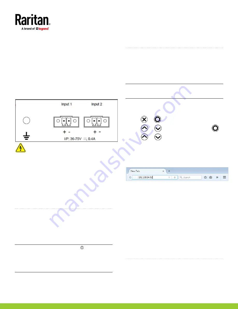
DC Power Connection for SRC-0103 and SRC-0803
SRC-0103 and 0803 include redundant (Input 1 and Input 2) DC
power inputs for typical DC48V power inputs. Each input is capable
of powering the system. If one fails, the SRC will not shut down.
Turn off power source before wiring the connection.
1. Strip the insulation around 12 mm from the end of each wire of
the power source.
2. Using provided connectors (not shown), fully insert each wire
into the correct termination point. Make sure DC48V(+) wire is
con
nected to “+” of Input (1 or 2) and DC48V(
-
) connects to “
-
”
of Input (1 or 2).
3. Use a screwdriver with a 2.5 mm wide shaft to tighten the
screws above each termination point to secure the wires, using
a torque of 0.196 N·m (2 kgf·cm).
4. GND symbol marks the protective earth connection. The fixed
screw for PE is included with the product.
QS Rule
Connecting SRC to Your Network
SRC can be connected to a wired or wireless network.
To make a wired connection:
1. Connect a standard network patch cable to either or both
Ethernet ports on the SRC.
2. Connect the other end of the cable to your LAN.
Note: The "green" Ethernet port labeled "ETH 10/100/1000"
supports up to 1000 Mbps so it is highly recommended for network
connection. If connecting both ports to the LAN, you must connect
them to two "different" subnets. If you are not sure whether the
device is connected to the same or different subnets, contact your
IT department.
To make a wireless connection:
1. Connect an appropriate USB wireless LAN adapter to the SRC.
2. Make sure the wireless LAN configuration is supported by your
SRC. See Wireless LAN Information.
QS Rule
Using a Web Browser
Step 1: Retrieve the IP Address
After connecting to a DHCP IPv4 network, an IPv4 address is
automatically assigned to your SRC. You can operate the front
panel display to retrieve the IPv4 address. See
Using the Front
Panel Display
(on page 6).
Tip: You can also retrieve the IPv4 address by connecting an iOS or
Android mobile device to SRC. See
Appendix A: Configuration via a
Mobile Device or PDView
(on page 6).
Using the Front Panel Display
To retrieve the IP address:
1. Press
or
to show the "Main Menu."
2. Press
or
to select "Device Info," and press
.
3. Press
or
until the device's IP address is displayed.
Step 2: Log in to the SRC Web Interface
1. In a web browser, enter the PDU IP address and login with the
default user credentials, accepting any security warnings.
▪
Default login: admin/raritan
Password change is enforced at first login.
Step 3: Configure SRC
After logging in to the SRC web interface, you can:
•
Choose Asset Strips for configuring connected asset strips.
•
Choose Peripherals for configuring connected environmental
sensor packages.
•
Choose SmartLock for configuring connected door handles or
SmartLock kit.
•
Choose Device Settings > Date/Time to configure the SRC with
the proper date and time or synchronize it with an NTP server.
The SRC device's time must be in sync with the LDAP server to
use LDAP authentication.
•
Choose other menu commands for configuring user profiles,
privileges, security, and more.
QS Rule
Appendix A: Configuration via a Mobile Device or
PDView
An iOS or Android mobile device, such as a smartphone or tablet,
can function as a local display. Android devices must support USB
"On-The-Go" (OTG).


