


25
Y
The parallel function is disabled
3.5.4.3 Press the scroll up key to execute special functions. The functions include buzzer ON (as in figure Q1),
buzzer OFF (as in figure Q2, Alarm silence for UPS Warning), and self-test OFF (as in figure R1) or self-test
ON (as in figure R2). The UPS will execute the battery test for ten seconds. If the self-test is successful it
will display figure E1; otherwise, it will display figure E2 and an error message at the same time.)
3. 5.5 UPS Default Settings and their alternatives
3.5.5.1. Make sure the UPS is not ‘On’. Press the ON and scroll down keys simultaneously for approximately
three seconds. The buzzer will sound twice and the LCD will display figure Q1, indicating that the UPS is in
setting mode.
3.5.5.2. To scroll through the options refer to section
3.4.4.2.
3.5.5.3. Except for Buzzer (figures Q1 and Q2) and Self-test (figures R1 and R2) all of the other default settings may
be changed by pressing the scroll up key.
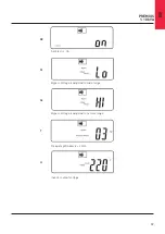
3.5.5.4. Figures S1 and S2 indicate the bypass input acceptable window. It follows the inverter output voltage.
Please refer specification for details.
3.5.5.5. Figure T indicates the bypass frequency window of the Inverter Output. The acceptable setting values are
±3 Hz and ±1 Hz.
3.5.5.6. Figure U indicates the acceptable Inverter Output Voltage. Possible values are 200, 208, 220, 230, or
240 VAC.
3.5.5.7. Figures V1, V2, V3 and V4 indicate the operation modes of the UPS. Possible values are Online, ECO
(Economical) mode, fixed 50 Hz Output, and fixed 60 Hz Output.
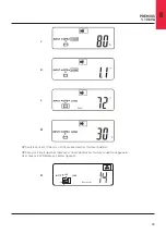
3.5.5.8. Figure W indicates the fine tune range of inverter voltage which can be set from -6 V to +6 V of rating
voltage. (The minimum adjustable scale is 0.1 V).
3.5.5.9. Figure X indicates the position of the UPS when the UPS is in Parallel mode. Possible positions are 1, 2, 3,
and 4. The position must be 1 if the UPS is not in Parallel mode.
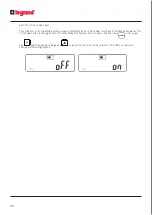
3.5.5.10. Figure Y indicates the parallel function status. ‘OFF’ and ‘ON’ separately indicate disabled and enabled.
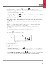
3.5.5.11. Figure Z indicates the last page of settable parameters.
3.5.5.12. After changing settings, you must press the enter key to save all of your changes and exit the setting
mode. Then the LCD will display figure AA, figure A1, then figure A2, and then figure B.
Z
* Press the Enter key to save changes
Parallel Mode
Содержание PREMIUS
Страница 1: ...PREMIUS 1 10 kVA User and Installation Manual ...
Страница 13: ...13 2 3 2 Rear Panel 1 kVA 3 kVA FMI 3 kVA FM 2 kVA FMI 2 kVA FM 1 kVA FMI ...
Страница 14: ...14 EN PREMIUS 1 10 kVA 5 kVA 6kVA FMI 5 kVA 6kVA FM 7 5 kVA 10kVA FM 7 5 kVA 10kVA FMI ...
Страница 39: ...39 6 Optional Interface Cards 6 1 RSE F RS 485 card 6 2 DCE Dry Contact 6 3 SNMP Card ...
Страница 50: ......