background image

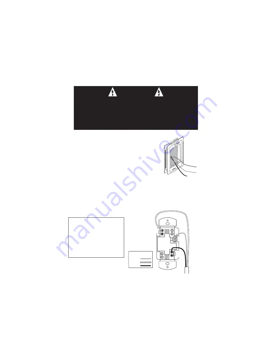
LINE

GND

Supply

Wires

NEUT

Wire Legend

Ground

Line

Neutral

INSTALLATION

1.  Disconnect power to circuit by turning circuit breaker OFF.

2.  Remove existing cover plate and switch. 

3.  Temporarily attach the steel subplate for the Miro 

cover plate to the wall box.

4.  Pull the wiring through the new Miro subplate. 

5.  Strip existing wires 1/2”. If two wires will be 

connected to the same terminal on a Miro device, both 
wires must be the same gauge (12AWG or 14AWG).

6.  Wire the LINE (black), NEUTRAL (white) and GND (green or bare) supply 

wires to the correspondingly marked screw terminals, according to the wiring 
diagram below. 

7.  Using the instructions provided with the Miro cover plate, attach the MRD6 to 

the metal subplate and to the wall box, then attach the Miro cover. 

8.  Switch the circuit breaker back ON.

CAUTION

TURN THE POWER OFF AT THE CIRCUIT BREAKER 

BEFORE INSTALLING THE DEVICE.

Install only using a UL Listed Miro cover plate and subplate 

assembly. If you do not have the proper Miro subplate for your 

application, obtain one from any supplier of Miro devices.

INSTALL IN COMPLIANCE WITH 

ALL APPLICABLE CODES & 

STANDARDS. 

Failure to follow these 

instructions may cause personal 

injury or equipment damage.

Steel
subplate

Wall box

Содержание MRD6 v2

Страница 1: ...MRD6 v2 Wireless Room Scene Controller Specifications Operating Voltage 120 277VAC 60Hz Operating Temperature 32 F to 104 F 0 C to 40 C Patents pending Installation Instructions ...

Страница 2: ...cenes in the room see MORE SCENES section You can install additional room scene controllers or MRH6 room scene remotes to control those scenes from multiple locations Note To control the entire house use a Miro wireless house scene controller a wall mounted MRD5 or a handheld MRH5 remote Miro Wireless Miro wireless devices use radio signals to communicate with each other to control lighting and ot...

Страница 3: ...re supply wires to the correspondingly marked screw terminals according to the wiring diagram below 7 Using the instructions provided with the Miro cover plate attach the MRD6 to the metal subplate and to the wall box then attach the Miro cover 8 Switch the circuit breaker back ON CAUTION TURN THE POWER OFF AT THE CIRCUIT BREAKER BEFORE INSTALLING THE DEVICE Install only using a UL Listed Miro cov...

Страница 4: ...cating house binding is complete Adding an MRD6 to an Existing Installation If you re adding or replacing a MRD6 in a Miro wireless installation that is already operating the new MRD6 must acquire the same House ID as the other Miro wireless devices in the house After the new MRD6 is powered up the LED should be solid yellow This indicates that it has not yet acquired a House ID To acquire the Hou...

Страница 5: ...device press on the device until the LED changes color Yellow flashing LED Included in room Green flashing LED NOT included in room If a device is NOT flashing see TROUBLESHOOTING 4 Return to the MRD6 used in step 2 Press for about 2 seconds the status LED stops flashing then all the status LEDs in the house turn green Adding an MRD6 to an Existing Room If you re adding an MRD6 in a room where room le...

Страница 6: ...D6 are included in each scene button except fan controls The following illustration shows the default operation for scene set 1 5 NOTES 1 Pressing and holding the paddle does not affect the operation of switched devices They will maintain their present state 2 If the lights were turned off using the default E scene button or any customized scene button programmed for 0 ALL OFF pressing and holding...

Страница 7: ...en Removing or Adding Devices to the Paddle On Function 1 Press on the MRD6 until the LED begins flashing about 2 seconds 2 Tap the paddle on the MRD6 The LEDs on all the Miro wireless devices begin to flash You now have 5 minutes to complete this process 3 To include or exclude a device press on the device until the LED changes color Yellow flashing LED Included in paddle operation Green flashing LED...

Страница 8: ...LED blinks twice about 2 seconds To assign scenes 11 15 simultaneously press and C until the LED blinks twice about 2 seconds To change the assignment back to scenes 1 5 simultaneously press and button A until the LED blinks twice about 2 seconds A 1 5 default B 6 10 C 11 15 LOCK ROOM CONFIGURATION The Lock Configuration function operates from a wireless Miro room level controller and prevents the ...

Страница 9: ...the scene controller LED flashes GREEN Go back to the previously locked device and press If it flashes green or yellow you have unlocked the house configuration If the device still flashes red the configuration may be locked by a room level scene controller such as the MRD6 or MRH6 Go to the room scene controller and simultaneously press and buttons B and E until the scene controller LED flashes GREEN S...

Страница 10: ...rference by one or more of the following measures Reorient or relocate the receiving antenna Increase the separation between the equipment and receiver Connect the equipment into an outlet on a circuit different from that to which the receiver is connected Consult the dealer or an experienced radio TV technician for help Caution Any changes or modifications to this device not explicitly approved by...

Отзывы: