background image

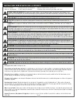
IMPORTANT SAFETY INSTRUCTIONS

DANGER HAZARDOUS

 VOLTAGE

The lightning flash with the arrowhead symbol, within an 

equilateral triangle is intended to alert the user to the 

presence of uninsulated dangerous voltage within the product’s enclosure that may be of sufficient magnitude to constitute a risk of electric shock to 

persons.

WARNING

: A warning alerts you to a situation that could result in serious personal injury or death.

CAUTION

: A caution alerts you to a situation that may result in minor personal injury or damage to the product and/or property.

NOTE

: A note is used to highlight procedures pertaining to the installation, operation, or maintenance of the product.

• Read these instructions.
• Keep these instructions.

• Heed all warnings.
• Follow all instructions.

• Clean only with dry cloth.
• Only use attachments/accessories specified by the manufacturer. 

WARNING

: Failure to read, understand and follow the following information can result in serious personal injury, damage to the 

equipment or voiding of the warranty. It is the responsibility of the Installer/User to ensure that this product is loaded according to 

specifications.

WARNING

: Exceeding the weight ratings listed can result in serious injury or damage to the equipment. It is the responsibility of the 

Installer/User to ensure the components installed do not surpass the weight ratings as an unstable condition can occur which may 

cause possible injury or damage.

CAUTION

: Note that during construction, there must be no possibility of personal injury, for example the squeezing of fingers or 

arms.

CAUTION

: If there is visible damage on the product, it must not be installed.

CAUTION

: Safety measures must be practiced at all times during the assembly of this product. Use proper safety equipment and 

tools for the assembly procedure to prevent personal injury.

CAUTION

: For loading, always put heavier items at the bottom of the bays, not near the top, in order to help prevent the possibility 

of the furnishing tipping over.

CAUTION

: The appliance is not intended for use by young children or infirm persons without supervision.

Safety Instructions

: Rack Mount

Elevated Operating Ambient

: If installed in a closed or multi-unit rack assembly, the operating ambient temperature of the rack 

environment may be greater than room ambient. Therefore, consideration should be given to installing the equipment in an environment 

compatible with the maximum ambient temperature (Tma) specified by the manufacturer.

Reduced Air Flow

: Installation of the equipment in a rack should be such that the amount of air flow required for safe operation of the 

equipment is not compromised.

Mechanical Loading

: Mounting of the equipment in the rack should be such that a hazardous condition is not achieved due to uneven 

mechanical loading.

Circuit Overloading

: Consideration should be given to the connection of the equipment to the supply circuit and the effect that 

overloading of the circuit might have on overcurrent protection and supply wiring. Appropriate consideration of equipment nameplate 

ratings should be used when addressing this concern.

Reliable Earthing

: Reliable earthing of rack-mounting equipment should be maintained. Particular attention should be given to supply 

connections other than direct connections to the branch circuit (e.g. use of power strips).

Disconnect Device (Pluggable Equipment)

: The socket-outlet shall be installed near the equipment and shall be easily accessible.

WARNING

: Middle Atlantic Products, electrical systems conform to and should be properly grounded in compliance with require-

ments of the current National Electrical Code or codes administered by local authorities. All electrical products may present a possible 

shock or fire hazard if improperly installed or used. Electrical products may bear the mark of a Nationally Recognized Testing 

Laboratory (NRTL) and should be installed in conformance with current local and/or the National Electrical Code.

Page 3

Содержание Middle Atlantic Forum

Страница 1: ...truction Sheet Thank you for purchasing a Forum collaboration suite Please read these instructions thoroughly before installing or assembling this product THANK YOU 100 00066 Rev B NOTE Free standing and floor to wall models shown ...

Страница 2: ...Using Top Small Device Storage and Bottom Rackmount Bays 13 14 Re Attaching the Front Panel to Your Display Stand 14 Selecting the Correct Interface Bracket Hardware for Your Display 14 15 Attaching Interface Brackets to the Back of Your Display 15 Attaching the Shroud and Mount to Your Display Stand 16 Hanging Your Display onto the Mount 17 Assembling Your Table if Purchased 17 19 Understanding C...

Страница 3: ... the bottom of the bays not near the top in order to help prevent the possibility of the furnishing tipping over CAUTION The appliance is not intended for use by young children or infirm persons without supervision Safety Instructions Rack Mount Elevated Operating Ambient If installed in a closed or multi unit rack assembly the operating ambient temperature of the rack environment may be greater t...

Страница 4: ...graves blessures des dommages à l équipement ou invalider la garantie Il est la responsabilité de l installateur utilisateur de s assurer que ce produit est chargé conformément aux spécifications Consignes de sécurité montage en rack Température de fonctionnement élevée Si installé dans un rack fermé ou à unités multiples la température ambiante de fonctionne ment de l environnement du rack peut ê...

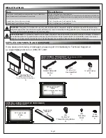
Страница 5: ...7 3901 10 Lever Lock Plate NOTE Pre Installed Inside Display Stand E Display Stand NOTE Free Standing and Floor to Wall models respectively A CHIEF GRADE 5 TOGGLER KIT Model Number FCAT1 NOTE Floor to Wall Display Stand Models Only 4x 20 x 2 Hex Head Bolt C 4x 20 Washer D 4x SNAPTOGGLE Anchor B Item Weight Rating Display Stand s Bottom Rackmount Storage Display Stand s Top Small Device Storage 50 ...

Страница 6: ... Screw R 3 Person Angle 5 Person Angle 3 Person Arc CHIEF FUSION FIXED DISPLAY MOUNT 4x M4 x 12mm Pan Head Screw I A 4x M4 x 20mm Pan Head Screw I A 4x M4 x 25mm Pan Head Screw I A 4x M5 x 12mm Pan Head Screw I A 4x M5 x 20mm Pan Head Screw I A 4x M5 x 25mm Pan Head Screw I A 4x M6 x 12mm Pan Head Screw I A 4x M6 x 20mm Pan Head Screw I A 4x M6 x 25mm Pan Head Screw I A 4x M8 x 20mm Pan Head Screw...

Страница 7: ...Number MDEA3 WH REQUIRED TOOLS WARNING Use tools with caution and follow all necessary safety protocols AVERTISSEMENT Utiliser des outils avec prudence et suivre tous les protocoles de sécurité nécessaires 2 Phillips Bit 2 Phillips Screwdriver Toothpick or Small Straw Adjustable Wrench Socket Awl Socket Protective Eyewear Socket Wrench 5 16 Socket Power Driver Drill Bit 7 16 Socket 3 32 Drill Bit ...

Страница 8: ... and additional reference covering the included Chief Fusion Fixed Display Mount and any optional Wiremold On Surface Primary MDSA10 WH Middle MDCA3 WH and End MDEA3 WH ModPower Units you may have purchased for your optional table s For more information refer to the following Forum product page at www legradav com https www legrandav com Products Technical_Furniture Collaboration Forum_Collaborati...

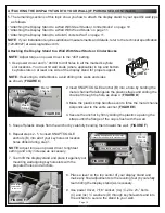
Страница 9: ...along top and bottom keyhole slot lines drawn during previous step as shown 4 Carefully team lift your display stand away from the wall WARNING This procedure requires at least one additional person AVERTISSEMENT Cette procédure nécessite au moins une personne supplémentaire WARNING The display stand must always bear its weight on its feet when wall mounted AVERTISSEMENT Le présentoir doit toujour...

Страница 10: ...essary 7 Team lift the display stand and place it against your mounting wall aligning keyhole slots with the prepared holes and anchors Plastic Cap Handles Metal Channel Making handles even forces metal channel perpendicular to entire anchor Slide plastic cap along straps FIGURE E 8 Place a level on the top center of your display stand and make any final adjustments to the leveling feet by careful...

Страница 11: ...TE When securing your display stand A to a solid concrete wall you must provide your own concrete anchors that support the weight ratings specified in Weight Ratings on page 5 Secure your display stand A to a solid concrete wall by using a procedure similar to Securing the Display Stand to a Wall With Steel Studs or Cinderblocks on page 10 INSTALLING AND CONFIGURING THE 10 LEVER LOCK PLATE NOTE On...

Страница 12: ...kets each kit sold separately installed in the lower sides of the display stand for clarity 3 Insert securing rivets J on the tab beneath the clip of the 10 plate to lock it in place NOTE Use 20x washers K for equipment mounting convenience 2 Attach the 10 Lever Lock plate F by inserting the side with the 2 tabs and no securing clip first Insert the tabs into the corresponding openings on the brac...

Страница 13: ...Bare frame of display stand shown for clarity 1 Load equipment into the top small device storage columns using Installing and Configuring the 10 Lever Lock Plate on page 11 and Installing the Lever Lock Kit If Purchased on page 12 as needed FIGURE K 2 Run cabling using knockouts between the top small device storage columns and the bottom rackmount bays as necessary FLOOR TO WALL DISPLAY STANDS ONL...

Страница 14: ...t any point during the overall installation and configuration process In addition to front door access to the bottom rackmount bays you can also access both the top small device storage and bottom rackmount bays from the back by carefully tugging at the magnetic sides of the back panel and opening back bay latch panels respectively FIGURE M The useable equipment depth of the bottom rackmount bays ...

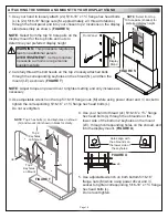
Страница 15: ...and other audio products available from Legrand or other providers before your display mount and display Before proceeding refer to the instructions provided with your accessory for the proper installation order 1 Carefully place your display facedown onto an appropriate work surface NOTE Center the interface brackets I B on your display so they do not extend past the top or bottom 2 Determine the...

Страница 16: ...nding holes on the shroud and into the display mount FIGURE U 1 Use your hand to loosely attach 2x 5 16 18 x 1 flange hex head bolts L to 2x 5 16 18 flange nuts M approximately 2 3 thread rotations through the front panel and into your chosen top 2 locations on the display stand assembly as shown FIGURE S NOTE Select from the top 10 hole pairs on the display mount for the top bolts and nuts to det...

Страница 17: ...u moins une personne supplémentaire WARNING Do not release your display until certain the top hook of each interface bracket is securely seated on the upper pole of the mount AVERTISSEMENT Ne relâchez pas votre écran tant que le crochet supérieur de chaque support d interface n est pas solidement fixé sur le pôle supérieur du support NOTE Tables models include 3 and 5 person angle tables and a cur...

Страница 18: ...RE X NOTE Adjust torque on power driver to lightest setting and only increase as necessary 3 Use power driver and Phillips bit to partially attach 2x 10 32 x thread forming screws R to the top inside of both table leg assemblies N approximately from the surface 4 With someone else holding one of the leg assemblies N carefully pick up the trough S and hook the keyholes over the 10 32 x thread formi...

Страница 19: ...of trough On 5 person angle tables there are 4x screw locations on front and back of trough FIGURE AB Screw Locations on 3 and 5 Person Angle Tables 18x and 20x Total Respectively V V 11 Use power driver Phillips bit and 12x 6x per panel 8 x 5 16 pan head sheet metal screws W through holes from the inside of the trough to attach your modesty panel pair X to corresponding sides of your table FIGURE...

Страница 20: ...nécessite au moins une personne supplémentaire NOTE Underside of arc table tops V shown without leg assemblies and troughs for clarity Table Locks FIGURE AE Front of Table Back of Table Back View of Table To appropriately rated receptacles To devices on your table To devices on your table To devices on your table FIGURE AD To appropriately rated receptacles V V 1 Carefully team lift each of your a...

Страница 21: ...ation may differ You may have purchased any number of optional Wiremold On Surface ModPower System Primary Middle or End units to provide power to your optional table s NOTE If purchased a primary ModPower unit is required to run any additional middle and end units A single primary unit may run power to an additional 7 units for a maximum of 8 total 3 Connect your unit s as specified in the On Sur...

Страница 22: ...9 5009 ca middleatlantic com av canada customerservice legrand com Middle Atlantic EMEA Technical Support P 31 495 726 003 av emea middleatlantic support legrand com Factory Distribution United States New Jersey California and Illinois Canada Ontario The Netherlands Weert At Legrand AV Inc we are always listening Your comments are welcome Legrand AV is an ISO 9001 and ISO 14001 Registered Company ...

Отзывы: