


58
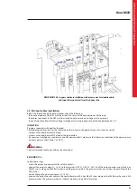
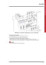
4.3
Power modules installation
Once all the electrical connections have been made, close the distribution panels and fix them by screwing all the hex
socket M6x16 screws along with M6 toothed washers.
It is then possible to move onto the insertion of the power modules into the UPS.
During the installation it is necessary to use the appropriate Personal Protective Equipment like protective gloves and
anti-accident shoes (see paragraph 2.3).
INDICATION
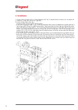
To guarantee the stability of the Keor MOD 125 cabinet, first install the power modules and only later the battery drawers.
Insert the power modules one at a time starting from the top of the cabinet.
Unscrew the four screws that fix the slot cover where the power module must be installed and save them.
Handle the power module from his sides and never from the front.
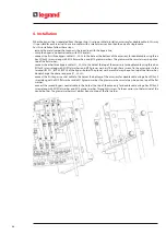
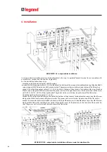
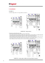
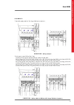
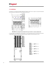
4. Installation
Содержание Keor MOD 100
Страница 1: ...Part LE11406AB 04 19 01 GF Keor MOD Installation and maintenance manual ...
Страница 2: ...2 EN ENGLISH 3 Keor MOD ...
Страница 20: ...20 4 Installation 3 4 5 ...
Страница 22: ...22 4 Installation 9 10 ...
Страница 24: ...24 4 Installation KEOR MOD 250 earthing bars ...
Страница 79: ...Keor MOD Installation and maintenance manual 79 6 3 3 Removal of the SSS drawer 1 2 3 4 ...
Страница 87: ...Keor MOD Installation and maintenance manual 87 ...
Страница 88: ...88 9 Mechanical characteristics ...
Страница 89: ...Keor MOD Installation and maintenance manual 89 ...
Страница 90: ...90 9 Mechanical characteristics ...
Страница 91: ...Keor MOD Installation and maintenance manual 91 9 2 Power module PM25 all the dimensions are in mm ...
Страница 92: ...92 9 Mechanical characteristics 9 3 Battery drawer all the dimensions are in mm ...
Страница 93: ...Keor MOD Installation and maintenance manual 93 9 4 Battery block all the dimensions are in mm ...