User Manual of iSV2-CAN Servo
www.leadshine.com
51
signal
13
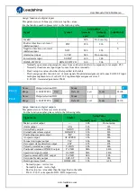
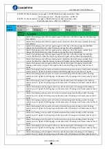
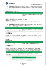
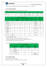
Search the homing point in negative direction, deceleration point is homing switch, homing
point is motor Z signal on the other side of homing switch, the rising edge on the other side of
homing switch must come before Z signal
14
Search the homing point in negative direction, deceleration point is homing switch, homing
point is motor Z signal on the other side of homing switch, the falling edge on the other side of
homing switch must come before Z signal
15
16
17-32
Similar with 1-14, but the deceleration point coincides with the homing point
33
Search the homing point in negative direction, homing point is motor Z signal
34
Search the homing point in positive direction, homing point is motor Z signal
35
Set the current position as homing point
Index
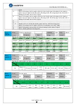
60FDH
Name
Status of digital input
Structure
VAR
Type
Dint 32
Access
R0
Mapping
TPDO
Mode
ALL
Range
0-ffff Default
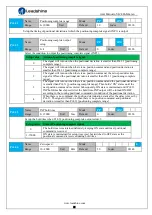
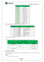
The bits of a 60FDh object are functionally defined as follow:
Bit31
Bit30
Bit29
Bit28
Bit27
Bit26
Bit25
Bit24
Z signal
Reserved
Reserved
Reserved
Touch
Probe 2
Touch
Probe 1
BRAKE
INP/V-COIN
/TLC
Bit23
Bit22
Bit21
Bit20
Bit19
Bit18
Bit17
Bit16
E-STOP
Reserved
Reserved
Reserved
Reserved
Reserved
SI14
SI13
Bit15
Bit14
Bit13
Bit12
Bit11
Bit10
Bit9
Bit8
SI12
SI11
SI10
SI9
SI8
SI7
SI6
SI5
Bit7
Bit6
Bit5
Bit4
Bit3
Bit2
Bit1
Bit0
SI4
SI3
SI2
SI1
Reserved
HOME
POT
NOT
Index
60FEH-0
1
Name
Output valid
Structure
VAR
Type
Uint 32
Access
RW
Mapping
RPDO
Mode
ALL
Range
0-ffff Default
0
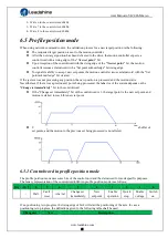
The bits of a 60FEh object are functionally defined as follow:
Bit
Sub-index
31~21
21
20
19
18
17
16
15~0
01h
Reserve
d
DO6 valid
DO5 valid
DO4
valid
DO3 valid
DO2 valid
DO1 valid
Reserved
Index
60FEH-0
2
Name
Output enable
Structure
VAR
Type
Uint 32
Access
RW
Mapping
Mode
ALL
Range
0-ffff Default
0
The bits of a 60FEh object are functionally defined as follow:
Bit
Sub-index
31~21
21
20
19
18
17
16
15~0
02h
Reserved
DO6
enable
DO5
enable
DO4
enable
DO3
enable
DO2
enable
DO1
enable
Reserved

