iEM-RS Series Modbus RS485 Integrated Stepper Motor
8
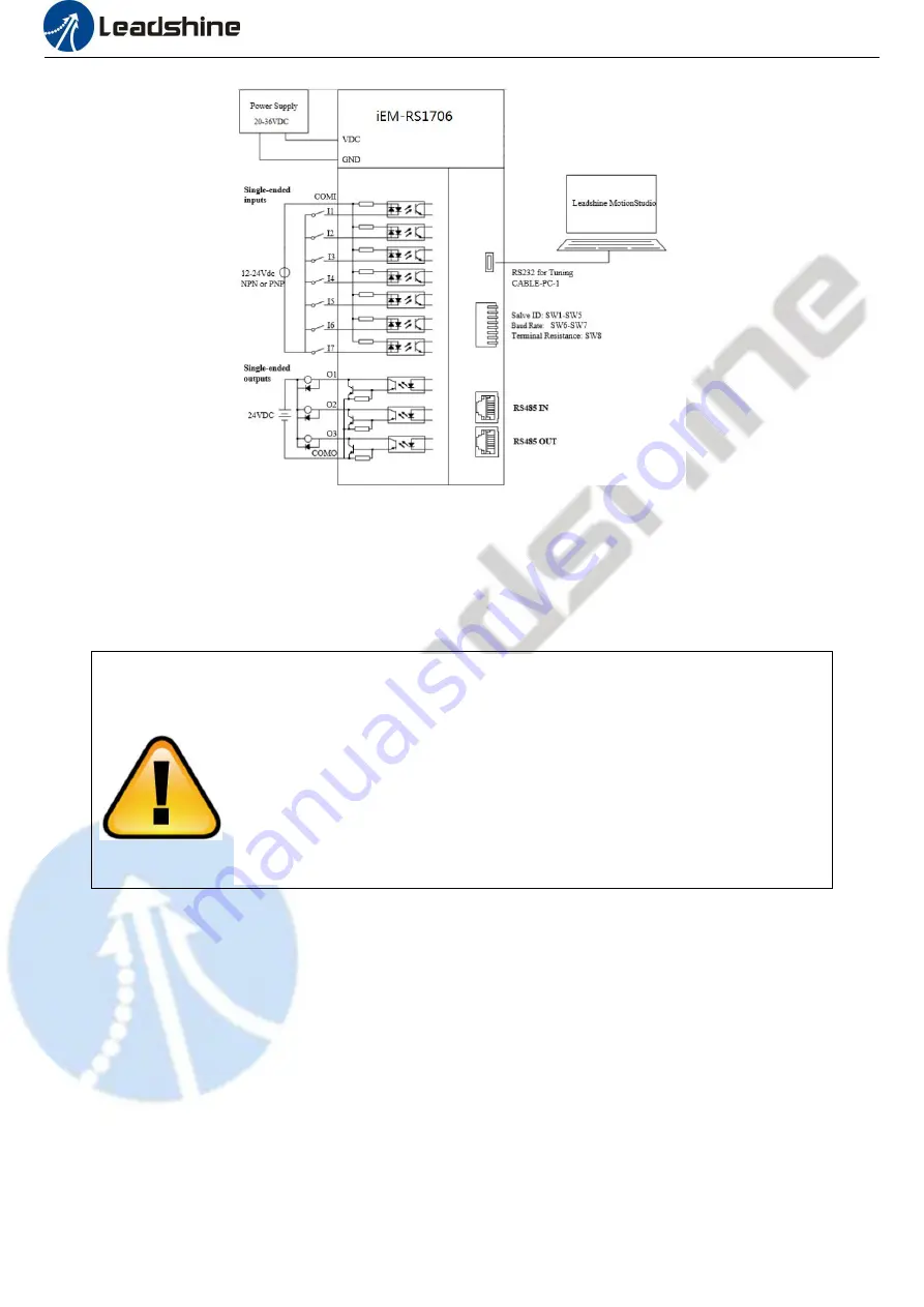
Figure 3.1 Wiring Instructions
Note:
(1) There are two RS485 communication ports above, one of them is input port which connects with master station or previous
slave, and the other is output port which connects with the following slave.
(2) Single-ended inputs I1, I2, I3, I4, I5, I6 and I7 connection types can be common-cathode and common-anode.
(3) Single-ended outputs connection type is common-anode
CAUTION
3.2.1 Power Supply Cable
Wire diameter: +VDC, GND terminal wire diameter≥0.3mm
2
(AWG15-22)
A noise filter which can improve anti-interference performance is recommended to be connected between power supply and
drive.
3.2.2 I/O Signal Cable
Wire diameter: I1 - I7, O1 - O3, COM wires diameter≥0.12mm
2
(AWG24-26)
Recommend to adopt shielded twisted pair cable with a length of less than 3 meters (the shorter the better).
Wiring: As far as possible away from the power line wiring, in order to prevent interference
Please connect surge absorber to inductive device, such as anti-parallel diode for DC coil, parallel RC-snubbers circuit for AC
coil.
Don’t hot plug the motor wiring, encoder wiring and RS232 communication
wiring during power on.
Be sure to check the connections and make sure the power lead polarity is correct,
or there could result in injury or fire.
Be sure wait for 5 minutes or longer to touch drives after turning off power
Be sure to give the power supply voltage dose not exceed the drive’s input range.
If using a motor with small phase current, be sure to modify the driver output
current before enabling the motor


