background image

iEM-RS Series Modbus RS485 Integrated Stepper Motor

45

01 06

62 00

00 41 56 42

Set PR mode to relative position mode

01 06

62 01

00 00 C7 B2

Set PR0 position high

01 06

62 02

27 10 2D 8E

Set PR0 position low

01 06

62 03

02 58 66 E8

Set PR0 velocity

01 06

62 04

00 32 56 66

Set PR0 acceleration

01 06

62 05

00 32 07 A6

Set PR0 deceleration velocity

01 06

60 02

00

10

37 C6

Trigger PR0 motion

Send when you need to stop:

01 06

60 02

00 40 37 FA

Emergency stop

(3)

Set PR0 to go in velocity mode, velocity is 300rpm

Commands:

01 06

62 00

00 00 02 17 B3

Set PR0 to velocity mode

01 06

62 03

01 2C 66 3F

Set PR0 speed value

01 06

60 02

00

10

37 C6

Trigger PR0 motion

Send when you need to stop:

01 06

60 02

00 40 37 FA

Emergency stop

(4)

Set PR1 to go absolute position mode, running distance -200000p (microstep is 10000)

Commands:

01 06

62 08

00 01 D6 70

Set PR1 mode

01 06

62 09

FF FC 07 C1

Set PR1 position high

01 06

62 0A

F2 C0 F3 40

Set PR1 position low

01 06

62 0B

02 58 E7 2A

Set PR1 speed value

01 06

62 0C

00 32 D7 A4

Set PR1 acceleration

01 06

62 0D

00 32 86 64

Set PR1 deceleration

01 06

60 02

00

11

F6 06

Trigger PR1 motion

Send when you need to stop:

01 06

60 02

00 40 37 FA

Emergency stop

(Note: -200000 is converted to hexadecimal as FFFCF2C0. You can enter the minus sign first, then 200000, and then enter the

minus sign again to display FFFCF2C0)

(5)

Set PR1 go velocity mode, speed value is 200rpm (microstep is 10000)

Commands:

01 06

62 08

00 02 96 71

Sets PR1 to velocity mode

01 06

62 0B

01 2C E7 FD

Set PR1 speed value

01 06

60 02

00

11

F6 06

Trigger PR1 motion

Send when you need to stop:

01 06

60 02

00 40 37 FA

Emergency stop

(6) Homing

Commands:

01 06

60 0A

00 00 B7 C8

Set homing method

01 06

60 0F

00 64 A6 22

Set homing speed high

01 06

60 10

00 1E 16 07

Set homing speed low

01 06

60 02

00 20 37 D2

Trigger Homing

Appendix A Parameters List

1. Modbus RTU Parameters

The Leadshine RS485 parameter data type is 32-bit data, and a parameter contains two registers, high 16 bits and low 16 bits,

but in practice most parameters only need to use the low 16 bits. When reading and writing multiple parameters in succession,

the high 16 bits of the parameter need to be used as the start.

Register

Address

Software

Parameter

No.

Name

Description

Range

Default

Value

Unit

0x0001

Pr0.00

Pulse/revolution

10000

200-51200

10000

P/R

0x0005

Pr0.02

Control mode source

Invalid

0-10

1

--

Содержание iEM-RS Series

Страница 1: ...l 2022 Leadshine Technology Co Ltd Address 15 20 F Block B Nanshan I Valley No 3185 Shahe West Road Nanshan District Shenzhen Guangdong 518055 China Tel 86 755 26409254 Fax 86 755 26402718 Web www leadshine com Sales sales leadshine com Support tech leadshine com ...

Страница 2: ... taken in the preparation of the book Leadshine assumes no responsibility for errors or omissions Neither is any liability assumed for damages resulting from the use of the information contained herein This document is proprietary information of Leadshine that is furnished for customer use ONLY Information in this document is subject to change without notice and does not represent a commitment on ...

Страница 3: ...ing a cover to prevent accidental touching by hands and parts cables etc Use double insulated or reinforced insulation for control power Do not use in places where water can be splashed Corrosive environments Do not use the product in the vicinity of flammable gases and combustible materials Do not use damaged Drivers and motors with missing parts Please set up an emergency stop circuit externally...

Страница 4: ...ied direction Make sure to keep the specified intervals between the inner surfaces of the drive control cabinet and other machines Do not pass the solenoid contactor in the wiring between the driver and the motor Please connect the power terminal and motor terminal firmly Keep a minimum distance of 10mm between the drive and the control cabinet or other equipment Allow at least 30mm of wiring spac...

Страница 5: ...N4 RS232 Tuning Port 6 3 1 4 DIP Switches 6 3 2 Wiring Instructions 7 3 2 1 Power Supply Cable 8 3 2 2 I O Signal Cable 8 3 2 3 RS485 Communication Cable 9 3 3 I O Connection 9 3 3 1 Digital Inputs 9 3 3 2 Digital Output 9 4 Modbus RTU 10 4 1 Communication Specifications 10 4 2 Modbus Function Codes FC 10 4 2 1 Read Holding Registers FC 03 11 4 2 2 Preset Single Register FC 06 12 4 2 3 Preset Mult...

Страница 6: ...OG 29 5 3 3 Quick Stop 30 5 4 PR Path 31 5 4 1 PR Parameters 31 5 4 2 PR Path Configuration 32 5 4 3 Other functions of PR 32 5 5 Trigger Methods 34 5 5 1 CTRG Trigger 34 5 5 2 IO Combination Trigger 35 5 5 3 Fixed Trigger 36 5 5 4 Immediate Trigger 36 6 Tuning Operations 38 6 1 Basic operation of Leadshine MotionStudio 38 6 1 1 Preparation and Steps 38 6 1 2 Operation of Trial Run 40 6 1 3 Operat...

Страница 7: ...nection RS485 port for motion control Protections for over voltage over current etc Compare with Step Direction Built in single axis control can save the PLC in most of point to point applications to reduce cost Built in rich diagnostic functions and input and output signals to setup easily Modbus brings more expansion possibility to add value 1 3 Application Scenarios Divided into simple hands on...

Страница 8: ...to turn off the switch signal to realize the PR motion which is simple to control and low cost design Users can also use PLC I O module to realize PR motion which is more intelligent than switch signal control Note The above drive pictures are for reference only it is actually an integrated stepper motor with drive ...

Страница 9: ...perature ranging from 20 to 65 4 F 149 F Store within a relative humidity ranging from 40 to 90 and non condensed Avoid any type of exposure to corrosive gases 2 2 2 Operating ambience conditions Temperature ranging from 0 to 50 The ambient temperature of drive for long term reliability should be under 40 Please install the drive in a well ventilated area Operation within a relative humidity rangi...

Страница 10: ...r 4 Figure 1 Mechanical specifications 3 Interface and Connection 3 1 Interface 3 1 1 Connectors Definition Name Description CN1 Input power connector CN2 Digital inputs and outputs connector CN3 RS485 communication connector CN4 RS232 tuning connector ...

Страница 11: ...DI1 is enabling signal default DI2 DI7 are GPIOs 2 DI2 I 3 DI3 I 4 DI4 I 5 DI5 I 6 DI6 I 7 DI7 I 8 COMI I 9 DO1 O Configurable Single ended Outputs Signals DO1 DO3 common cathode or common anode Max 24V 100mA GPIOs 10 DO2 O 11 DO3 O 12 COMO O Note 1 DI1 is normally closed default by Enable signal It means the motor is locked shaft after the driver powered on 2 When using Brake output signals you n...

Страница 12: ...hown as below 1 Slave ID SW1 SW5 off 1 on 0 Slave ID SW1 SW2 SW3 SW4 SW5 default on on on on on 1 factory off on on on on 2 on off on on on 3 off off on on on 4 on on off on on 5 off on off on on 6 on off off on on 7 off off off on on 8 on on on off on 9 off on on off on 10 on off on off on 11 off off on off on 12 on on off off on 13 off on off off on 14 on off off off on 15 off off off off on 16 ...

Страница 13: ... is default all are on the Slave ID can be configured by the PC software 2 Baud Rate SW6 SW7 Baud Rate SW6 SW7 115200 Default on on 38400 Factory off on 19200 on off 9600 off off Note 1 When the SW6 SW7 is default all are off the Baud Rate can be configured by the PC software 3 Terminal Resistance Selection SW8 SW8 ON terminal resistance is valid SW8 OFF terminal resistance is invalid Factory sett...

Страница 14: ...Cable Wire diameter I1 I7 O1 O3 COM wires diameter 0 12mm2 AWG24 26 Recommend to adopt shielded twisted pair cable with a length of less than 3 meters the shorter the better Wiring As far as possible away from the power line wiring in order to prevent interference Please connect surge absorber to inductive device such as anti parallel diode for DC coil parallel RC snubbers circuit for AC coil Don ...

Страница 15: ... 3 1 Digital Inputs The connections of input signals are as below Figure 3 3 Input Interface Connection 3 3 2 Digital Output Figure 3 4 Output Interface Wiring Note 1 The power supply 12 24VDC above is provided by user and if the polarity of power supply is reversed it will damage the drive 2 Digital output is OC output with the maximum capacity of 100mA 24V recommended 50mA 24V the provided power...

Страница 16: ...Protocol Modbus RTU ASCII is not supported Slave ID 0 broadcast 1 31 valid sub devices Numbers Parameter setting Function code FC Function code FC Function 0x03 Read single or multiple data 0x06 Write value to single data 0x10 Write value to multiple data Check Mode CRC 16 Left is Low bit Right is high bit Message Length Variable the max length is 200byte Single message communication rate of RS485...

Страница 17: ...ow CRC Low High High Example A Read the value of a single register peak current Send message 01 03 01 91 00 01 D3 1B Receive message 01 03 02 00 0A 38 43 Details as following Master slave data Message 01 03 01 91 00 01 D3 1B Description Slave ID FC Register address Number of registers read CRC Slave master data Message 01 03 02 00 0A 38 43 Description Slave ID FC Number of bytes returned Value of ...

Страница 18: ...ister Query Master to Slave Preset Single Register Response Slave to Master Slave ID 00 1F Slaver ID 00 1F FC 06 FC 06 Address of register to write to High Address of register written to High Low Low Value to write High Value written to register High Low Low CRC Low CRC Low High High Example C Write the value of a single register peak current Send message 01 06 01 91 00 20 DD 7B Receive message 01...

Страница 19: ...er Slave ID 00 1F Slaver ID 00 1F FC 10 FC 10 Address of first register to write to High Address of first register written to High Low Low Total number of registers to write to High Total number of registers written to High Low Low Number of data bytes in message 2 bytes per register CRC Low Value1 to write High High Low Value2 to write High Low CRC Low High Example E Write multiple registers conf...

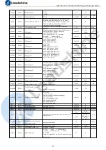
Страница 20: ...ed regardless of the IO signal status 0 1 0 0x00A1 Pr2 00 Command filter time To configure the time for internal command filtering 0 512 15 0 1m s 0x0145 Pr4 02 DI1 input 1 Default is normal open N O type it can be set to normal closed N C type by setting the corresponding port 0x80 DI1 is enable default N C type input 0 invalid 7 alarm clearing 8 enable also can be set by 0x00F 0x20 Trigger comma...

Страница 21: ...SW7 are all OFF it can be set by PC software 0 6 4 0x01BF Pr5 23 RS485 ID When SW1 SW5 are all ON it can be set by PC software 0 127 1 0x01C1 Pr5 24 RS485 data type selection 0 8 bit data even check 2 stop bits 1 8 bit data odd check 2 stop bits 2 8 bit data even check 1 stop bit 3 8 bit data odd check 1 stop bit 4 8 bit data no check 1 stop bit 5 8 bit data no check 2 stop bits 0 11 4 0x01C3 Pr5 ...

Страница 22: ...tage 0x40 Current sampling fault 0x80 Failed to lock shaft 0x200 EEPROM fault 0x100 Auto tuning fault 4 3 2 Input and Output Parameters Register Address Par in software Definition Description Range Default Unit 0x0145 Pr4 02 SI1 DI1 1 SI1 is set to enable by default N C normally closed 2 Other inputs are N O normally open by default 3 The value of bit7 of each input register is set normally closed...

Страница 23: ...6 0xA6 Home switch ORG 0x27 0xA7 Path Address 0 ADD0 0x28 0xA8 Path Address 1 ADD1 0x29 0xA9 Path Address 2 ADD2 0x2A 0xAA Path Address 3 ADD3 0x2B 0xAB Clear Error CLR 0x07 0x87 Enable SRV ON 0x08 0x88 4 3 3 Smooth Filter Time Setting for Digital Inputs This section describes the setting of the value of each bit of the registers of the 7 inputs where the filtering time is set by the high 8 bits S...

Страница 24: ...3208 to Pr4 02 to achieve the above configuration Example 2 IO input port 1 is set to enable function Normally closed Filter time 10ms default The register value is configured as 0000 0000 1000 1000 which translates to 136 in decimal i e write 136 to Pr4 02 to achieve the above configuration Routine 3 IO input port 7 is set to JOG2 function Normally open Filter time 500ms The register configuratio...

Страница 25: ...eters are reset to factory Write 0x2244 Save all mapping parameters into EEPROM Write 0x4001 JOG CW Need to write once at least 50ms Write 0x4002 JOG CCW Status Word of Saving Parameter Register address Definition Attributes Description 0x1901 status word R Show 0x5555 Saving parameter OK Show 0xAAAA Saving parameter fault Note 1 The read value is 0x1111 when no save instruction has been executed ...

Страница 26: ...ode 4 4 2 Drive Alarm Codes and Troubleshooting Register Address definition operation unit description 0x2203 Current alarm R Below table Error code and cause The green light is always on after the drive power on When the error is occurred the drive will stop working and red light will be flashed indicates the current error code Whatever error occurs the user need to power off the drive and restar...

Страница 27: ...age error but can not clear over current error 2 There are two methods to clear the current alarm one is via Leadshine MotionStudio and the second is via external I O 3 If the current error cannot be cleared please check the drive Clear history error History error All history error records can be cleared by Leadshine MotionStudio 4 5 Register Mapping Continuous Read Write Function Address descript...

Страница 28: ...R0 velocity Message Example Conditions Drive ID is 1 motor is stationary 1 Mapping Master Slave 01 10 0F 10 00 0A 00 00 01 00 09 00 A1 01 91 01 67 01 73 02 33 02 43 60 2E 62 03 4B 43 Slave Master 01 10 0F 10 00 0A 42 DF 2 Read and write Master Slave 01 03 0F 00 00 0A C6 D9 Slave Master 01 03 14 27 10 05 87 00 0F 00 3C 00 FA 00 03 0F A0 00 5A 00 01 00 00 00 56 F4 3 Mapping parameter save instructio...

Страница 29: ...nd outputs 2 and 3 are not on Pr8 28 S code current output value register address 0x601C Path number S code at completion bit8 10 S code at start up bit0 2 S code setting value Remarks Path 1 001 000 Binary 1000 0001 1000 0000 Hexadecimal 0x8180 At start up No level at all three outputs Completion Output port 1 has level PR8 28 1 Path 2 011 010 Binary 1000 0011 1000 0010 Hexadecimal 0x8382 At star...

Страница 30: ...JOG JOG teaching function The JOG velocity and JOG Acc Dec can be set Limit Protect the machine by limiting the working area range Positive negative limit switch by digital input Soft limit setting Acc Dec limit can be set Note Soft limit is valid after homing completed Quick stop The movement stop immediately when the quick stop input is on which is valid at PR mode only PR Path Select the PR pat...

Страница 31: ... by register address 0x600A or Leadshine software If the homing direction is positive then it is positive limit switch homing Conversely the negative limit homing Home switch Set by register address 0x600A or Leadshine software If the motor turns toward the home switch when zeroing it will use the home switch it touches as the home point if the motor turns in the opposite direction when zeroing it...

Страница 32: ...r8 13 is high 16 bits and Pr8 14 is low 16 bits Pr8 14 0x600E Homing stop position low bits Pr8 15 0x600F Homing high velocity The 1st segment velocity of homing unit rpm Pr8 16 0x6010 Homing low velocity The 2nd segment velocity of homing unit rpm Pr8 17 0x6011 Homing Acc Acc of homing unit ms 1000rpm Pr8 18 0x6012 Homing Dec Dec of homing unit ms 1000rpm Note Generally homing to find the zero po...

Страница 33: ...iEM RS Series Modbus RS485 Integrated Stepper Motor 27 2 Home Switch at Positive Direction 3 Home Switch Negative Limit Switch ...

Страница 34: ...iEM RS Series Modbus RS485 Integrated Stepper Motor 28 4 Home Switch at Negative Direction 5 2 3 Homing by Limit Switch 1 Positive Limit Switch 2 Negative Limit Switch ...

Страница 35: ... bits 0x6008 Pr8 08 Soft limit H 32767 0x8000 Soft limit negative high bits 0x6009 Pr8 09 Soft limit L 32767 0 Soft limit negative low bits 0x6016 Pr8 22 Soft limit quick stop time Deceleration time after triggering the soft limit unit ms 5 3 2 JOG The JOG function allows fine tuning of the drive or fine adjustment of the position of the device or forward and reverse velocity operation of the moto...

Страница 36: ... effect in real time The path motion can also be triggered by external IO SI1 is set to enable input by default normally closed SI2 is set to JOG used for positive directional velocity operation SI3 is set to JOG used for negative directional velocity operation SI6 is set to JOG velocity 2 used for JOG high and low velocity switching SI4 is set to trigger signal CTRG which is used to trigger path ...

Страница 37: ...Non overlapping 1 Overlapping Bit6 0 absolute position 1 relative position Bit8 13 Jump to the corresponding PR path 0 15 bit14 JUMP 0 No jump 1 jump Pr9 01 0x6201 Position H High 16 bit Pr9 02 0x6202 Position L Low 16 bit Pr9 03 0x6203 velocity Unit rpm Pr9 04 0x6204 Acc Unit ms 1000rpm Pr9 05 0x6205 Dec Unit ms 1000rpm Pr9 06 0x6206 Pause time Pause time after the command is stopped Pr9 07 0x620...

Страница 38: ...on off means signal input off PR path DI1 ADD0 DI2 ADD1 DI3 ADD2 DI4 ADD3 DI5 CTRG Path 0 off off off off on Path 1 on off off off on Path 2 off on off off on Path 3 on on off off on Path 4 off off on off on Path 5 on off on off on Path 6 off on on off on Path 7 on on on off on Path 8 off off off on on Path 9 on off off on on Path 10 off on off on on Path 11 on on off on on Path 12 off off on on o...

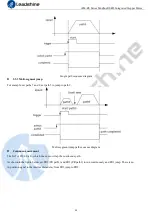
Страница 39: ...nd 9 set path 5 to jump to path 9 Multi segment jump path sequence diagram Continuous movement The bit5 of Pr9 00 is 0 which does not overlap the continuous path As shown in the figure below set PR1 PR path1 and PR2 PR path2 to run continuously and PR1 jump There is no in position signal in the intermediate delay from PR1 jump to PR2 ...

Страница 40: ...rrupting and abandoning the current path under trigger and runs another path directly which is similar as Interrupt priority of function As below example interrupt the PR1 PR path1 to run PR2 PR oath2 Interrupt function timing sequence 5 5 Trigger Methods 5 5 1 CTRG Trigger When the path triggered by CTRG it can be configured for rising edge triggering or double edge triggering No falling edge tri...

Страница 41: ...RG SI1 and SI2 are all on the path 3 is triggered As shown in the table below on means signal input on off means signal input off IO running path SI1 ADD0 SI2 ADD1 SI5 CTRG Path 0 off off on Path 1 on off on Path 2 off on on Path 3 on on on 5 5 2 IO Combination Trigger The configuration is done by the parameter Pr8 26 Combination trigger mode With the IO combination trigger there is no need to set...

Страница 42: ...mmended Steps as below 1 Firstly configure required homing and path it can be set through controller PLC software after power on or through Leadshine PC software 2 Enable drive 3 Write corresponding command to the 0x6002 to realize the selection and startup of each action Par Register address Definition Description Pr8 02 0x6002 Trigger register Write corresponding command to the 0x6002 to realize...

Страница 43: ...tion code 0x10 FC Function code 0x10 3 ADDR Address 0x62 ADDR Address 0x62 4 0x00 0x00 5 NUM1 Number of Word 0x00 NUM Actually written Number of 0x00 6 0x08 0x08 7 NUM2 Number of Byte 0x10 CRC check code Lo Hi 8 9 Pr9 00 Mode XXXX 10 11 Pr9 01 High position XXXX 12 13 Pr9 02 Low position XXXX 14 15 Pr9 03 velocity XXXX 16 17 Pr9 04 Acceleration XXXX 18 19 Pr9 05 Deceleration XXXX 20 21 Pr9 06 Dela...

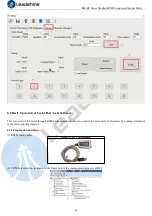
Страница 44: ...hich supports Windows 7 and Windows 10 systems 6 1 1 Preparation and Steps 1 RS232 Tuning cable CABLE PC 1 Pin Definition It is recommended that users order this cable directly from Leadshine not to make it yourself 2 USB to RS232 converter sometimes it needs to manually install the drive program 3 COM port selection as shown in the figure below the communication port is COM3 4 Connect tuning soft...

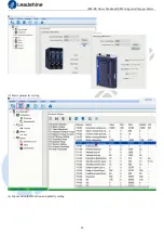
Страница 45: ...iEM RS Series Modbus RS485 Integrated Stepper Motor 39 5 Basic parameter setting 6 Input and output function and polarity setting ...

Страница 46: ...ick OK Then in the parameter management window click the Save button to prevent the parameter values from being lost after the drive is powered off 6 1 2 Operation of Trial Run Trial run lets the motor to achieve forward and reverse rotation or repeat motion The operation steps are as follows ...

Страница 47: ...tor 41 6 1 3 Operation of PR Function 1 This window can set the CTGR trigger and Homing parameters of PR motion 2 This window is the PR path parameter setting including operation mode target position speed value etc Double click to modify parameters ...

Страница 48: ... download and save as follows 3 Manually run the PR path As shown in the figure below the default is the motion parameter of PR0 As long as click Start the motor will run according to the path of PR0 If click PR1 in step 4 the motor will be forced to switch to the path of PR1 Click step 3 to stop motor ...

Страница 49: ...This is to control the motor through RS485 communication user can realize the movement of the motor by sending commands to the corresponding registers 6 2 1 Preparation and Steps 1 RS485 tuning cable RS458 to USB User provided 2 COM port selection as shown in the figure below the communication port is COM3 ...

Страница 50: ...al port tool software A complete command 01 06 62 00 00 41 56 42 6 2 3 Command Cases of Modbus RTU 1 Set PR0 to go absolute position mode running distance 200000p microstep 10000 Commands 01 06 62 00 00 00 01 57 B2 Set PR0 mode to absolute position mode 01 06 62 01 00 03 87 B3 Set PR0 position high 01 06 62 02 0D 40 32 D2 Set PR0 position low 01 06 62 03 02 58 66 E8 Set PR0 speed value 01 06 62 04...

Страница 51: ...1 06 60 02 00 11 F6 06 Trigger PR1 motion Send when you need to stop 01 06 60 02 00 40 37 FA Emergency stop Note 200000 is converted to hexadecimal as FFFCF2C0 You can enter the minus sign first then 200000 and then enter the minus sign again to display FFFCF2C0 5 Set PR1 go velocity mode speed value is 200rpm microstep is 10000 Commands 01 06 62 08 00 02 96 71 Sets PR1 to velocity mode 01 06 62 0...

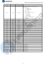
Страница 52: ... type it can be set to normal closed N C type by setting the corresponding port 0x80 0 invalid 0x20 command completed 0x21 path completed 0x22 homing completed 0x23 in position completed 0x24 brake output 0x25 alarm output 0 65535 0 0x0159 Pr4 12 DO2 output 2 0 65535 0 0x015B Pr4 13 DO3 output 3 0 65535 0 0x0167 Pr4 19 Delay of brake released Keep default normally 0 1500 250 ms 0x0169 Pr4 20 Delay...

Страница 53: ...o tuning can be modified 0 1500 300 0x023B Pr7 05 Current loop KP 0 1024 100 0x023D Pr7 06 Current loop Kc Invalid 0 32767 300 0x0243 Pr7 09 Over voltage threshold Invalid 0 1000 90 V 0x1003 Motion status Read only Bit NO Read value 1 means Bit0 Fault Bit1 Enable Bit2 Running Bit4 Command completed Bit5 Path completed Bit6 Homing completed 0x1801 Control word Write value Function 0x1111 Reset curr...

Страница 54: ...ration time after quick stop unit ms Pr8 26 0x601A IO combination trigger mode selection 0 Disable IO combination triggering factory 1 Enable IO combination triggering activated after homing is completed 2 Enable IO combination triggering nothing to do with homing recommended Pr8 27 0x601B IO combination filter time Unit ms Pr8 28 0x601C S code current output value Pr8 29 0x601D Read PR Warning 0 ...

Страница 55: ...s stopped Pr9 07 0x6207 Special parameter PR Path 0 maps directly to Pr8 02 Others are reserved Pr9 08 0x6208 Motion of Path 1 Pr9 09 0x6209 Position H Pr9 10 0x620A Position L Pr9 11 0x620B velocity Pr9 12 0x620C Acc Pr9 13 0x620D Dec Pr9 14 0x620E Pause time Pr9 15 0x620F Special parameter Pr9 16 0x6210 Motion of Path 2 Pr9 17 0x6211 Position H Pr9 18 0x6212 Position L Pr9 19 0x6213 velocity Pr9...

Отзывы: