background image

IT

ALIANO

POLSKI

ESP
AÑOL

FRANCAIS

DEUTSCH

ENGLISH

13

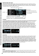
MICROPHONE STATION STATUS DISPLAY

To view the status information of individual microphone stations, adjust the individual volume and in order to make changes in the micro-

phone station menu, press the switch corresponding to the desired microphone station (in this example RX1 = MIC 1). To adjust the volume, 

use the pressure rotary encoder PUSH TO ENTER (rotate right = increase volume, rotate left = lower volume). In order to make changes in 

the microphone station menu, press on the pressure rotary encoder.

Switch RX 1 - RX 4

Battery status

Frequency channel and frequency group

- Active antenna and radio signal level
- Audio signal level with Peak display (PK)
- Volume adjustment

Microphone station with priority
Mute function activated (mute)

Microphone station number and radio frequency

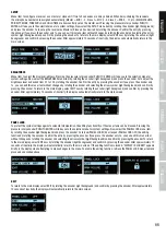
IR SYNC RUN

To synchronise the microphone station with the radio channel set in the receiver, bring the infrared port of the microphone station in direct visual 

contact with the infrared port of the receiver (distance approx. 10 cm) and turn on the microphone station. Press the switch corresponding to 

the desired microphone station (in this example RX 1 = MIC 1) and then press the pressure rotary encoder 

PUSH TO ENTER. Now select the IR SYNC RUN menu item by rotating the encoder (light background) and press the encoder once more to 

launch the synchronisation process. After a few seconds, the process is completed and the display of the microphone station switches for a 

short time to “IR SYNC

”, confirming successful synchronisation. When daisy-chaining the receivers, the microphone station numbers are 

assigned automatically (Master = MIC 1 - 4, Slave 1 = MIC 5 - 8, Slave 2 = MIC 9 - 12, Slave 3 = MIC 13 - 16, Slave 4 = MIC 17 - 20). The 

microphone station numbers are automatically transmitted to the microphone station during the synchronisation process and are shown on the 

display. To cancel the operation, press the encoder. To return to the main display, select EXIT now by rotating the encoder (light background) 

and confirm by pressing the encoder. Then press the switch corresponding to the desired microphone station (RX 1 - 4). After approximately 10 

seconds of inactivity, the display will automatically return to the main screen.

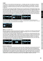
FREQ AUTO RUN

Automatic frequency search (frequency scan) to determine an interference-free radio frequency in the current environment and to allow for 

optimal reception. For this purpose, leave the corresponding transmitter off, but other radio systems turned on, if necessary. To start the 

automatic frequency search, press the switch corresponding to the desired microphone station (in this example RX 1 = MIC 1) and press 

the pressure rotary encoder PUSH TO ENTER. Now select the FREQ AUTO RUN menu item by rotating the encoder (light background). To 

confirm the operation, press the encoder. Progress is now indicated on the display by an animation and the scanning process is completed 

after a few seconds (to cancel, press the encoder). The resulting frequency is automatically enabled and, as in “IR SYNC RUN”, you can now 

switch on the transmitter and synchronise it with the receiver. To return to the main display, select EXIT now by rotating the encoder (light 

background) and confirm by pressing the encoder. Then press the switch corresponding to the desired microphone station (RX 1 - 4). After 

approximately 10 seconds of inactivity, the display will automatically return to the main screen.

CHANNEL

Menu item to manually adjust the frequency channel. Press the switch corresponding to the desired microphone station (in this example RX 

1 = MIC 1) and then press the pressure rotary encoder 

PUSH TO ENTER. Now select the CHANNEL menu item by rotating the encoder (light background) and press the encoder 2x to adjust the 

frequency channel as desired by rotating the encoder. Confirm the entry by pressing the encoder. If you press the encoder only 1x, you can 

exit this menu item without changes by rotating the encoder and selecting the arrow symbol (light background) and confirm by pressing the 

encoder. To return to the main display, select EXIT now by rotating the encoder (light background) and confirm by pressing the encoder. Then 

press the switch corresponding to the desired microphone station (RX 1 - 4). After approximately 10 seconds of inactivity, the display will 

automatically return to the main screen. Synchronise the microphone station with the radio frequency set in the receiver as described in IR 

SYNC RUN. 

Note:

 Only frequency channels which are not already used by another microphone station can be set.

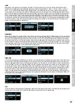
SQUELCH

The squelch control prevents unwanted background noise when the transmitter is turned off. In addition, sudden background noises are suppressed 

when the signal transmitted from the transmitter to the receiver is not strong enough (for instance because of excessive distance) Set the squelch 

control (with the transmitter switched off) to the lowest setting, which still effectively suppresses background noises. With an increased squelch 

level and in unfavourable conditions, the transmission range may decrease. Press the switch corresponding to the desired microphone station (in 

this example RX 1 = MIC 1) and then press the pressure rotary encoder 

PUSH TO ENTER. Now select the SQUELCH menu item by rotating the encoder (light background) and press the encoder 2x to adjust the squelch 

level as desired (00 - 50 dB) by rotating the encoder. Confirm the entry by pressing the encoder. If you press the encoder only 1x, you can exit this 

menu item without changes by rotating the encoder and selecting the arrow symbol (light background) and confirm by pressing the encoder. To 

return to the main display, select EXIT now by rotating the encoder (light background) and confirm by pressing the encoder. Then press the switch 

corresponding to the desired microphone station (RX 1 - 4). After approximately 10 seconds of inactivity, the display will automatically return to the 

main screen.

EXIT 

(in the microphone station menu)

To return to the main display, select EXIT on the encoder by rotating the encoder (light background) and confirm by pressing the encoder. 

Then press the switch corresponding to the desired microphone station (RX 1 - 4). After approximately 10 seconds of inactivity, the display 

will automatically return to the main screen.

BATTERY STATUS

The battery status of the microphone station will appear in the display and is constantly updated. When the batteries are fully charged, the 

symbol  

  ( 

 = approx. 70%, 

 = approx. 30%) will appear. As soon as the charge of the batteries is low, the display on the transmitter 

will show “LOW BATTERY” and the display on the receiver “LOW BATTERY” approximately every 4 seconds, and the number of the microphone 

station with low batteries will be displayed. Replace the batteries immediately.

Содержание 4049521207266

Страница 1: ...USER S MANUAL BEDIENUNGSANLEITUNG MANUEL D UTILISATION MANUAL DE USUARIO INSTRUKCJA OBS UGI MANUALE D USO U 500 CS4 4 CHANNEL WIRELESS CONFERENCE SYSTEM LDU500CS4 SERIES...

Страница 2: ...4 PUPITRE 35 UTILISATION 36 42 EN CAS DE PROBL ME 42 CARACT RISTIQUES TECHNIQUES 43 44 D CLARATIONS FABRICANT 44 ESPA OL MEDIDAS DE SEGURIDAD 45 46 INTRODUCCI N 46 47 CONEXIONES CONTROLES E INDICADORE...

Страница 3: ...ered device This equipment may only be repaired by authorized qualified personnel 19 Clean the equipment using a dry cloth 20 Comply with all applicable disposal laws in your country During disposal o...

Страница 4: ...ng antenna Increase the separation between the equipment and receiver Connect the equipment into an outlet on a circuit different from that to which the receiver is connected Consult the dealer or an...

Страница 5: ...e attached to the front of the receiver 7 Screw holes for 19 rack mounting Overview of the frequency ranges LDU505CS4 Wireless Conference System 554 586 MHz LDU506CS4 Wireless Conference System 662 69...

Страница 6: ...Connect the audio link OUT socket of the last slave unit in the device chain to the audio link IN socket of the penultimate slave unit etc Use the audio link IN socket of the master unit at the beginn...

Страница 7: ...equency 19 POWER MUTE Dual function switch 1 To turn the transmitter on press the switch briefly to turn it off press and hold for approx 3 seconds 2 When turned on press the switch briefly to activat...

Страница 8: ...tating the encoder from 00 to 25 Confirm the entry by pressing the encoder If you press the encoder only 1x you can exit this menu item without changes by rotating the encoder and selecting the arrow...

Страница 9: ...s 1 4 microphone stations This setting applies to all devices and can only be carried out on a device that is configured as a master unit if two to five units are daisy chained depending on the system...

Страница 10: ...l as desired from 01 to 10 by rotating the encoder 1 lowest threshold 10 highest threshold Confirm the entry by pressing the encoder If you press the encoder only 1x you can exit this menu item withou...

Страница 11: ...ncoder only 1x you can exit this menu item without changes by rotating the encoder and selecting the arrow symbol light background and confirm by pressing the encoder To return to the main display sel...

Страница 12: ...chronisation process and are shown on the display To cancel the operation press the encoder To return to the main display select EXIT now by rotating the encoder light background and confirm by pressi...

Страница 13: ...der PUSH TO ENTER Now select the SQUELCH menu item by rotating the encoder light background and press the encoder 2x to adjust the squelch level as desired 00 50 dB by rotating the encoder Confirm the...

Страница 14: ...n Check the batteries in the microphone station Receiver Display light is off Check the power supply in the transmitter Receiver Reception is not displayed on antenna A or B Microphone Station Device...

Страница 15: ...humidity in operation 20 80 non condensing 20 80 non condensing 20 80 non condensing Dimensions W x H x D 484 x 44 x 243mm 484 x 44 x 243mm 484 x 44 x 243mm Weight 2 45kg 2 45kg 2 45kg Accessories in...

Страница 16: ...current warranty conditions and limitations of liability at http www adamhall com media shop downloads documents manufacturersdeclarations pdf To request warranty service for a product please contact...

Страница 17: ...ein aktives Ger t handelt Dieses Ger t darf nur von autorisiertem Fachpersonal repariert werden 19 Verwenden Sie zur Reinigung des Ger ts ein trockenes Tuch 20 Beachten Sie alle in Ihrem Land geltend...

Страница 18: ...0 Hz Hochpassfilter der den Nahbesprechungseffekt und K rperschall wirksam reduziert Ein kontrastreiches OLED Display zeigt Funkfrequenz Batteriestatus die Nummer der Sprechstelle Gruppe und Kanal an...

Страница 19: ...kkappen befestigen die BNC Adapter an der Frontblende und verbinden die BNC Antennenanschl sse auf der R ckseite mit den BNC Adaptern in der Frontblende kurze Antennenkabel und BNC Adapter im Lieferum...

Страница 20: ...ie den Audio Link Anschluss OUT der letzten Slave Einheit in der Ger tekette mit dem Audio Link Anschluss IN der vorletzten Slave Einheit usw Verwenden Sie den Audio Link Anschluss IN der Master Einhe...

Страница 21: ...UTE Taster mit Doppelfunktion 1 Zum Einschalten des Sender kurz auf den Taster dr cken zum Ausschalten dr cken und f r ca 3 Sekunden halten 2 In eingeschaltetem Zustand den Taster kurz dr cken um die...

Страница 22: ...on 00 bis 25 anzupassen Best tigen Sie die Eingabe durch Dr cken auf den Geber Wenn Sie nur 1x auf den Geber dr cken k nnen Sie diesen Men punkt ohne Ver nderungen vorzunehmen verlassen indem Sie durc...

Страница 23: ...g gilt ger te bergreifend und kann ausschlie lich auf der Einheit vorgenommen werden die als Master Einheit konfiguriert ist falls zwei bis f nf Einheiten kaskadiert sind Systembedingt ist immer eine...

Страница 24: ...er von 01 bis 10 einzustellen 1 niedrigster Schwellenwert 10 h chster Schwellenwert Best tigen Sie die Eingabe durch Dr cken auf den Geber Wenn Sie nur 1x auf den Geber dr cken k nnen Sie diesen Men p...

Страница 25: ...eber dr cken k nnen Sie diesen Men punkt ohne Ver nderungen vorzunehmen verlassen indem Sie durch Drehen am Geber das Pfeilsymbol ausw hlen hell hinterlegt und durch Dr cken auf den Geber best tigen U...

Страница 26: ...echstellennummern automatisch vergeben Master MIC 1 4 Slave 1 MIC 5 8 Slave 2 MIC 9 12 Slave 3 MIC 13 16 Slave 4 MIC 17 20 Die Sprechstellennummer wird beim Synchronisierungsvorgang automatisch an die...

Страница 27: ...ebenger usche noch wirksam unterdr ckt werden Mit zunehmender St rke der Rauschunterdr ckung kann unter ung nstigen Umst nden die bertragungsreichweite verringert werden Dr cken Sie auf den Taster der...

Страница 28: ...f nger Displaybeleuchtung ist abges chaltet berpr fen Sie die Stromversorgung des Empf ngers Empf nger Empfang wird weder auf Antenne A noch B angezeigt Sprechstelle Ger t ist eingeschaltet Ladezustan...

Страница 29: ...ik Display Betriebsspannung 12 V DC 1000 mA 12 V DC 1000 mA 12 V DC 1000 mA Temperaturbereich 5 C 40 C 5 C 40 C 5 C 40 C Relative Luftfeuchte Betrieb 20 80 nicht konden sierend 20 80 nicht konden sier...

Страница 30: ...fend R TTE 1999 5 EG bzw RED 2014 53 EU ab Juni 2017 Niederspannungsrichtlinie 2014 35 EU EMV Richtlinie 2014 30 EU RoHS 2011 65 EU Die vollst ndige Konformit tserkl rung finden Sie unter www adamhall...

Страница 31: ...de quelque fa on que ce soit teignez le imm diatement et d branchez sa prise secteur s il s agit d un appareil aliment Cet appareil ne doit tre r par que par un personnel autoris 19 Pour le nettoyage...

Страница 32: ...la fr quence HF utilis e l tat des piles le num ro du poste du groupe et du canal La r ponse en fr quence s tend de 60 Hz 16 kHz Pour un r glage rapide et confortable du syst me les circuits du r cep...

Страница 33: ...ace avant et reliez les embases BNC pour antenne sur le panneau arri re aux adaptateurs BNC de la face avant c bles d antenne courts et adaptateurs BNC sont livr s Vous pouvez alors fixer les antennes...

Страница 34: ...o Link OUT d un appareil Slave au connecteur Audio Link IN de l appareil Slave suivant etc La cha ne de r cepteurs se reboucle sur le connecteur Audio Link IN de l appareil Master 14 DATA LINK IN OUT...

Страница 35: ...l metteur sous tension appuyez bri vement sur la touche pour l teindre maintenez la touche enfonc e pendant environ 3 secondes 2 L metteur se trouvant d j sous tension appuyez bri vement sur la touch...

Страница 36: ...votre entr e appuyez sur la molette touche Si vous appuyez une seule fois sur la molette touche vous pouvez abandonner l l ment de menu sans modification il suffit de s lectionner en tournant la mole...

Страница 37: ...t de 1 4 Ce r glage s applique tous les postes et ne peut se r gler que sur le r cepteur Master si vous avez cascad plusieurs appareils de 2 5 La conception du syst me implique qu un porte est ouvert...

Страница 38: ...valeur de seuil la plus faible 10 valeur de seuil la plus lev e Validez cette valeur en appuyant sur la molette Si vous appuyez une seule fois sur la molette touche vous pouvez abandonner l l ment de...

Страница 39: ...te touche vous pouvez abandonner l l ment de menu sans modification il suffit de s lectionner en tournant la molette l ic ne en forme de fl che qui passe en surbrillance puis de valider en appuyant su...

Страница 40: ...ter MIC 1 4 Slave 1 MIC 5 8 Slave 2 MIC 9 12 Slave 3 MIC 13 16 Slave 4 MIC 17 20 Les num ros de postes sont transmis automatiquement aux postes lors de la synchronisation du syst me et apparaissent su...

Страница 41: ...cepteur Pour des valeurs de Squelch lev es si les conditions HF sont d favorables la port e du syst me peut se trouver r duite Appuyez sur la touche correspondant au poste d sir par exemple RX1 MIC 1...

Страница 42: ...oste R cepteur Le r tro clairage de l cran est d sactiv V rifiez l alimentation secteur du r cepteur R cepteur Il est indiqu si la r ception s ef fectue via l antenne A ou l antenne B Poste L appareil...

Страница 43: ...raphique OLED Tension Alimentation 12 V cont 1000 mA 12 V cont 1000 mA 12 V cont 1000 mA Temp rature de Fonction nement 5 C 40 C 5 C 40 C 5 C 40 C Taux d Hygrom trie Relative en Fonctionnement 20 80 r...

Страница 44: ...0 groupes de 15 fr quences 180 10 groupes de 18 fr quences Nombre de Groupes 6 10 10 Connecteur Microphone XLR sym trique XLR sym trique XLR sym trique Tension d Alimentation Microphone 28 V 28 V 28 V...

Страница 45: ...inmediatamente el equipo y desenchufe el cable el ctrico si se trata de un equipo activo nicamente un t cnico especialista debe reparar el equipo 19 Para limpiar el equipo utilice un pa o seco 20 Pro...

Страница 46: ...a frecuencia el estado de la bater a el n mero de unidades de conferencia el grupo y el canal La banda de audio transmitida va de 60 Hz a 16 kHz Para poder configurar el sistema de forma r pida y f ci...

Страница 47: ...adaptadores BNC al panel frontal y conecte las tomas de antena BNC del panel posterior a los adaptadores BNC del frontal los latiguillos de antena y los adaptadores BNC est n incluidos Ahora ya puede...

Страница 48: ...T del ltimo equipo esclavo de la cadena con el conector Audio Link IN del pen ltimo equipo esclavo y as sucesivamente Use el conector Audio Link IN del equipo maestro de la cadena 14 DATA LINK IN OUT...

Страница 49: ...doble funci n 1 Pulse brevemente el bot n para encender el transmisor o mant ngalo pulsado durante 3 segundos para apagar el transmisor 2 Cuando est encendido pulse brevemente el bot n para activar o...

Страница 50: ...ntrol giratorio y luego g relo para ajustar el nivel de 00 a 25 Para confirmar el valor pulse de nuevo el control Si pulsa el control giratorio una sola vez puede salir de esta opci n de men sin cambi...

Страница 51: ...cionar la opci n NOM quedar resaltada pulse 2 veces el control y luego g relo para seleccionar el n mero de 1 a 4 de unidades de conferencia abiertas de forma simult nea Para confirmar el valor pulse...

Страница 52: ...ER para abrir el men de selecci n de ajustes del equipo Gire el control para seleccionar la opci n HOLD TIME quedar resaltada pulse 2 veces el control y luego g relo para seleccionar el tiempo de mant...

Страница 53: ...trol giratorio una sola vez puede salir de esta opci n de men sin cambiar los par metros para ello gire el control para seleccionar el s mbolo de flecha quedar resaltada y pulse el control para confir...

Страница 54: ...e el bot n asignado a la unidad de conferencia en el ejemplo RX 1 MIC 1 y luego pulse el control giratorio PUSH TO ENTER Mediante el control giratorio seleccione la opci n FREQ AUTO RUN quedar resalta...

Страница 55: ...r los par metros para ello gire el control para seleccionar el s mbolo de flecha quedar resaltada y pulse el control para confirmar Para volver a la pantalla principal seleccione EXIT con el control g...

Страница 56: ...la pantalla est apagada Compruebe la alimentaci n el ctrica del receptor Receptor no indica recepci n ni por la antena A ni por la B Unidad de conferencia el equipo est encendido Las pilas est n bien...

Страница 57: ...temperatura operativa 5 C a 40 C 5 C a 40 C 5 C a 40 C Humedad relativa operativa 20 a 80 sin condensaci n 20 a 80 sin condensaci n 20 a 80 sin condensaci n Dimensiones An Al F 484 44 243 mm 484 44 24...

Страница 58: ...no debe mezclarse con otros residuos industriales Alimentaci n fantasma del micr fono 28 V 28 V 28 V Respuesta en frecuencia 60 16 000 Hz 60 16 000 Hz 60 16 000 Hz Sensibilidad de entrada Nivel m x d...

Страница 59: ...uszkodzone w inny spos b nale y je natychmiast wy czy i od czy od gniazda sieciowego je li urz dzenie jest aktywne Napraw takiego urz dzenia mo e wykona tylko autoryzowany personel specjalistyczny 19...

Страница 60: ...a a Wysokokontrastowy wy wietlacz OLED wy wietla informacje na temat cz stotliwo ci stanu baterii numeru terminalu grupy i kana u Zakres transmisji audio wynosi 60 Hz 16 kHz Szybkie i wygodne ustawien...

Страница 61: ...towa adapter BNC z przodu obudowy a nast pnie po czy z cza antenowe BNC z ty u z adapterami BNC z przodu kr tki kabel antenowy i adapter BNC w zestawie Teraz nale y zamontowa anteny na przedniej stron...

Страница 62: ...z dze ze z czem Audio Link IN przedostatniej jednostki Slave itd a cuch urz dze powinien rozpoczyna si od z cza Audio Link IN jednostki Master 14 DATA LINK IN OUT Z cza do kaskadowania maksymalnie pi...

Страница 63: ...tliwo ci radiowej 19 POWER MUTE Przycisk o podw jnej funkcji 1 Nacisn kr tko przycisk nadajnika aby go w czy Nacisn i przytrzyma przycisk przez 3 sekundy aby go wy czy 2 Nacisn kr tko przycisk po w cz...

Страница 64: ...do 25 obracaj c pokr t em Potwierdzi zmian ustawie poprzez naci ni cie pokr t a Po jednokrotnym naci ni ciu pokr t a mo na opu ci t pozycj menu bez zmiany ustawie poprzez obr cenie pokr t a w celu wy...

Страница 65: ...ie to wp ywa na inne urz dzenia i mo na je zmienia wy cznie z poziomu urz dzenia kt re skonfigurowane zosta o jako jednostka Master w przypadku kaskadowania od dw ch do pi ciu urz dze ze wzgl du na wy...

Страница 66: ...to ci w zakresie od 01 do 10 1 najni sza warto progowa 10 najwy sza warto progowa Potwierdzi zmian ustawie poprzez naci ni cie pokr t a Po jednokrotnym naci ni ciu pokr t a mo na opu ci t pozycj menu...

Страница 67: ...a Po jednokrotnym naci ni ciu pokr t a mo na opu ci t pozycj menu bez zmiany ustawie poprzez obr cenie pokr t a w celu wybrania symbolu strza ki jasne pod wietlenie i naci ni cie pokr t a w celu potw...

Страница 68: ...ie Master MIC 1 4 Slave 1 MIC 5 8 Slave 2 MIC 9 12 Slave 3 MIC 13 16 Slave 4 MIC 17 20 Podczas procesu synchronizacji numery terminali zostan automatycznie przes ane do terminali i pokazane na wy wiet...

Страница 69: ...ry skutecznie t umi niepo dane d wi ki Wraz ze wzrostem g o no ci t umienie szum w mo e w niekorzystnych warunkach spowodowa zmniejszenie zasi gu transmisji Nacisn przycisk przypisany do danego termin...

Страница 70: ...odbioru anten A i B Sprawdzi czy terminal jest w czony Sprawdzi baterie terminalu Odbiornik pod wietlenie wy wietlacza jest wy czone Sprawdzi zasilanie odbiornika Odbiornik brak powiadomie dotycz cych...

Страница 71: ...tlacz graficzny OLED Napi cie robocze 12 V DC 1000 mA 12 V DC 1000 mA 12 V DC 1000 mA Zakres temperatur pracy od 5 C do 40 C od 5 C do 40 C od 5 C do 40 C Wilgotno wzgl dna w rodowisku pracy 20 80 bez...

Страница 72: ...uzgodnionych umownie warunk w utylizacji urz dze Niniejszy produkt nie mo e by utylizowany razem z innymi odpadami przemys owymi Czu o wej ciowa mikrofonu maks Poziom 100mV 1V depending on attenu ati...

Страница 73: ...pegnerlo immediatamente e staccare la spina se si tratta di un dispositivo attivo La riparazione del dispositivo deve essere affidata esclusivamente a personale qualificato autorizzato 19 Per la puliz...

Страница 74: ...della batteria il numero della postazione microfonica il gruppo e il canale L inter vallo di trasmissione audio compreso tra 60 Hz e 16 kHz Per una configurazione rapida e agevole del sistema il ricev...

Страница 75: ...ck Rimuovere i cappucci fissare gli adattatori BNC al pannello frontale e collegare le prese delle antenne BNC sul pannello posteriore con gli adattatori BNC sul pannello frontale i cavi per antenna c...

Страница 76: ...di dispositivi con il connettore Audio link IN della penultima unit Slave e cos via Utilizzare il connettore Audio link IN dell unit master all inizio della catena di dispositivi 14 DATA LINK IN OUT C...

Страница 77: ...adio 19 POWER MUTE Tasto con doppia funzione 1 Per attivare il trasmettitore premere brevemente il tasto per disattivare premere e tenere premuto per circa 3 secondi 2 Con il trasmettitore acceso prem...

Страница 78: ...r impostare il volume desiderato tra 00 e 25 Confermare l inserimento premendo la manopola Premendo la manopola una sola volta si pu uscire da questa voce di menu senza apportare modifiche in tal caso...

Страница 79: ...impostazione si applica a tutto il dispositivo e pu essere effettuata unicamente sull unit configurata come unit master se sono collegate a cascata da due a cinque unit il sistema prevede che sia sem...

Страница 80: ...soglia pi basso 10 valore soglia pi alto Confermare l inserimento premendo la manopola Premendo la manopola una sola volta si pu uscire da questa voce di menu senza apportare modifiche in tal caso ba...

Страница 81: ...la una sola volta si pu uscire da questa voce di menu senza apportare modifiche in tal caso basta ruotare la manopola per selezionare il simbolo freccia su sfondo chiaro e confermare premendo la manop...

Страница 82: ...ori i numeri delle postazione microfonica vengono assegnati automaticamente master MIC 1 4 slave 1 MIC 5 8 slave 2 MIC 9 12 slave 3 MIC 13 16 slave 4 MIC 17 20 Con la sincronizzazione il numero di pos...

Страница 83: ...ncrementando la soppressione del rumore possibile che in condizioni sfavorevoli la portata della trasmissione si riduca Premere il tasto assegnato alla postazione microfonica desiderata nell esempio R...

Страница 84: ...re l alimentazione del ricevitore Ricevitore la ricezione non viene visualizzata sull antenna A n B Postazione microfonica il dispositivo acceso Condizioni di carica delle batterie OK Verificare se la...

Страница 85: ...000 mA 12 V DC 1 000 mA 12 V DC 1 000 mA Intervallo temperatura di esercizio Da 5 C a 40 C Da 5 C a 40 C Da 5 C a 40 C Umidit relativa in esercizio Da 20 a 80 senza condensa Da 20 a 80 senza condensa...

Страница 86: ...azione della frequenza a infrarossi attenuazione rego labile filtro passa alto 130 Hz cassa rinforzata Sincronizzazione della frequenza a infrarossi attenuazione regolabile filtro passa alto 130 Hz ca...

Страница 87: ...ITALIANO POLSKI ESPA OL FRANCAIS DEUTSCH ENGLISH 87...

Страница 88: ...Adam Hall GmbH Daimlerstrasse 9 61267 Neu Anspach Germany Tel 49 0 6081 9419 0 Fax 49 0 6081 9419 1000 web www adamhall com e mail mail adamhall com WWW LD SYSTEMS COM REV 01...

Отзывы: