


GB-13
D
GB
F
NL
I
E
42
46
44
43
45
42
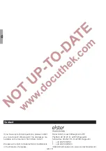
▷
Tighten the nuts in two cycles in a crosswise
fashion. Torque for ECOMAX
®
0 – 3: 18 Nm,
ECOMAX
®
4 – 5: 35 Nm.
47
Connect the grounding cable.
48
Connect the gas line to the gas insert.
49
Connect voltage to the system.
50
Open the gas and air supply.
5
Check for tightness, see page 9 (Tightness
5
Start the burner, see page 8 (Commission-
DANGER
Risk of explosion and poisoning in case of
burner adjustment with an air deficiency!
Ad-
just the gas and air supply so that the burner is
always operated with excess air – otherwise CO
will form in the furnace chamber. CO is odourless
and poisonous! Conduct a flue gas analysis.
5
Produce a maintenance report.
Assistance in the event of
malfunction
DANGER
Electric shocks can be fatal! Before working on
possible live components, ensure the unit is discon-
nected from the power supply.
Risk of injury! Burner heads have sharp edges.
Fault-clearance must only be undertaken by author-
ized trained personnel.
▷
If no fault is detected when checking the burner,
proceed to the automatic burner control unit and
check for faults in accordance with the relevant
operating instructions.
?
Faults
!
Cause
•
Remedy
?
Burner does not function?
!
Valves do not open.
•
Check the voltage supply and wiring.
!
Gas inlet pressure is too low.
•
Check the filter for dirt.
•
Check the gas supply.
!
Air inlet pressure is too low.
•
Check fan and air supply.
!
Gas and air pressures on the burner are too low.
•
Check the restrictors.
•
Check/adjust the start rate setting, see operating
instructions for solenoid valve.
!
Automatic burner control unit signals no fault.
•
Check the device fuse.
•
Note the automatic burner control unit operating
instructions.
!
Short-circuit of the UV sensor.
•
Replace the UV sensor.
•
Note the UV sensor operating instructions.
!
Automatic burner control unit signals a fault.
•
Check the ionization cable.
•
Check the ionization current (minimum ionization
current 5 µA and signal stable?).
•
Check whether the burner is adequately ground-
ed.
•
Note the automatic burner control unit operating
instructions.
!
No ignition spark is created.
•
Check the ignition cable.
•
Check the voltage supply and wiring.
•
Check whether the burner is adequately ground-
ed.
Содержание ECOMAX Series
Страница 17: ...GB 17 D GB...


