2
OPERATION:
A. Front Panel
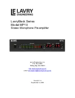
The MP10 has three toggle switches on the front panel. There is an individual gain
adjustment for each channel, and a three position toggle switch to enable or disable the
phantom power for each channel. Large numeric digital displays show both the level
during normal operation, and back panel settings on power-up. There is also a wide
range LED level meter to facilitate gain setting and display possible overloads.
B. AC Power Switch and Initialization
The AC power switch is used to turn the power “On” or “Off” on the MP10. When
powered on, the unit initializes for about 10 seconds. During initialization, the gain
displayed by the numeric digital displays start at a minimum setting, then “ramp up” to the
levels that were set before the power was turned “Off.” The numeric displays then switch
to displaying the settings of the rear panel switches while the meter display “scans”
through the segments. Once initialization is complete, the numeric displays revert to the
gain display.
C. Gain
The gain is adjustable for each channel in one dB steps from 20 to 75 dB. Use of a
digitally controlled analog gain circuit allows for precise adjustment and reset-ability,
while maintaining outstanding low-noise and distortion characteristics over a very wide
range of gain. The left channel gain is adjusted using the toggle switch labeled
“Up/Down” to the left of the LEFT GAIN display, and the right channel is adjusted using
the toggle switch labeled “Up/Down” to the right of the RIGHT GAIN display.
The wide gain range accommodates both the vast majority of microphones available and
output levels suitable for both unbalanced “-10” and balanced “+4” level inputs. When the
output switch is set to “unbal,” the maximum output level is reduced by 6 dB from the
maximum level for balanced operation of +24 dBu. Even so, when feeding the output of
the MP10 to an unbalanced “-10” level input, care should be taken to set the gain so that
the peak signal level displayed on the MP10’s meter does not exceed “-6.” This
corresponds to the (approximate) 12 dB difference between the peak level for a “+4dBu”
and “-10dBV” signal. Exceeding this level when feeding a “-10” input may result in
clipping at the input stage of the “-10” device.
D. Meters
The output level is displayed on two 14 segment LED meters covering the range from -46
to 0 dB’s below peak output level. For balanced outputs peak level is +24 dBu, and for
unbalanced outputs peak level is +18 dBu.
E. Phantom Power for Condenser Microphones
The three position momentary toggle switch located between the two numeric GAIN
displays (labeled “phan.”) is used to 48V Phantom power for each channel,
individually. Clicking the switch once in the up direction will enable or disable the
Phantom power on the left channel, and clicking the switch once in the down direction
toggles the right channel Phantom power on or off. The decimal point in the GAIN display
of the appropriate channel illuminates when the Phantom power is enabled.
F. Impedance Switch
There is a toggle switch labeled “hi z” or “lo z” located on the back panel between the
input and output XLR connectors. The “lo z” position should be used for low impedance
Dynamic or Condenser microphones, and the “hi z” position optimizes the input
impedance for Ribbon microphones. When AC power is applied, the setting of this switch
is displayed in the right GAIN display during initialization.
Содержание MP10
Страница 2: ......


