LAVAZZA BLUE LB 300 CLASSY MINI Скачать руководство пользователя страница 25

Technical support maintenance manual

Rel. 0.00 / June 2018

21

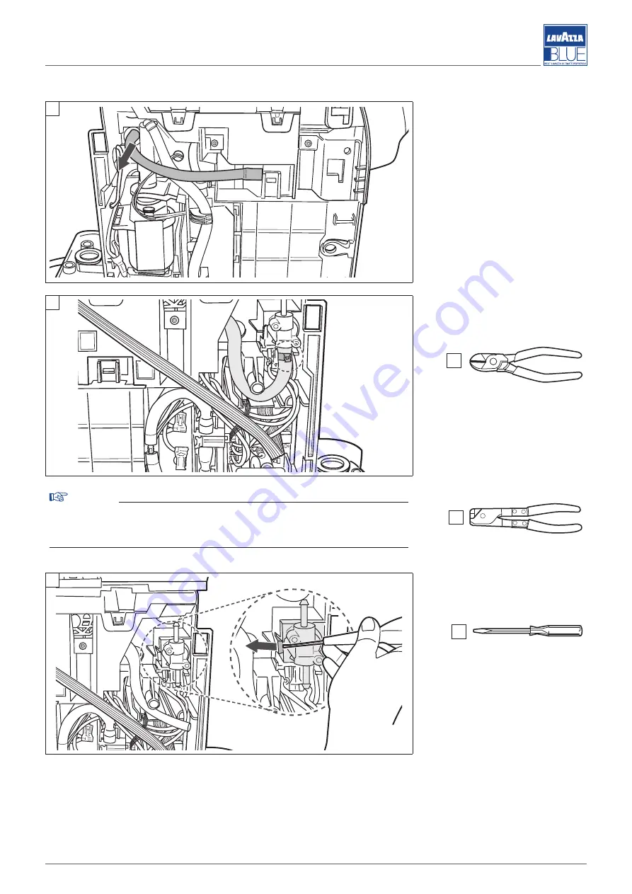
13.2. REMOVING THE 2-WAY SOLENOID VALVE

Figura A

: disconnect the dis-

charge hose on the other side of 
the machine.

Figura B

: cut the high pressure 

SILICON HOSE clamp and re-
move the hose.

Warning

Take care not to tear the hose. 
During reassembly, the clamp must be replaced and tightened with the 
OETIKER pliers.

Figure C

: pry on the locking lever 

and push the solenoid valve out-
ward.

D

A

B

G

G

H

C

Содержание BLUE LB 300 CLASSY MINI

Страница 1: ...LB 300 CLASSY MINI TECHNICAL SUPPORT MAINTENANCE MANUAL ...

Страница 2: ...tion 06 2018 Copyright LAVAZZA S p A To request technical support contact TECHNICAL SERVICE LAVAZZA sending an e mail to technicalservice lavazza it phoning n 39 011 2398429 sending a fax to n 39 011 23980466 or consulting the website http ts inlavazza it ...

Страница 3: ...2 RESETTING TO FACTORY DEFAULT DOSE 7 8 ROUTINE MAINTENANCE 7 8 1 DESCALING 7 8 2 CLEANING 7 9 TROUBLESHOOTING 9 9 1 INDICATION AND SOLUTION OF MOST COMMON PROBLEMS 9 10 RECOMMENDED TOOLS FOR DISASSEMBLY AND ASSEMBLY OPERATIONS 11 11 GENERAL OPERATIONS 12 11 1 DISCONNECTING ELECTRIC WIRINGS 12 11 2 REMOVAL OF HYDRAULIC CONNECTIONS 13 12 DISASSEMBLING THE BODY 15 12 1 EXTRACTING THE DRIP TRAY USED ...

Страница 4: ...Technical support maintenance manual Rel 0 00 June 2018 IV Page left intentionally blank ...

Страница 5: ...vice website 1 1 2 MESSAGES USED Attention ATTENTION messages indicate even high risk dan ger for the technician The operations described after this message must be carried out with the ut most attention and in maximum safety using per sonal protective equipment Warning WARNING messages are displayed before proce dures which could cause damage to the machine if not complied with Environment ENVIRO...

Страница 6: ...the vicinity of flammable and or explosive substances and or in a fire risk atmosphere use non original spare parts make any type of technical modifications of the ma chine not included in the standard diagnostic and re pair procedures Incaseoffire usecarbondioxide CO2 fireextinguishers Do not use water or powder extinguishers If you must perform an unintended job or intervention following a proce...

Страница 7: ...SPOSAL TREATMENT This product conforms to Directive 2012 19 EU and the relevant national implementations The symbol of the crossed out wheeled bin ap plied to the appliance and or packaging indi cates that at the end of its useful life the prod uct must be collected separately from other waste At the end of its life the user must hand over the appliance to suitable facilities for the separate coll...

Страница 8: ...ght 260 mm Weight 3 5 kg 5 1 3 TECHNICAL FEATURES Power supply voltage 220 240 V Power supply frequency 50 60 Hz Installed power 1250 W Water tank capacity 700 cc Boiler type THERMOBLOCK Water presence check Using the volumetric meter Used capsules container capacity 5 Power saving function After 30 minutes of inactivity Absorption in Stand by 0 5 W Dosage Programmable espresso and free doses 5 2 ...

Страница 9: ...7 Drip tray grid 8 On Free dose dispensing button 9 On Espresso dispensing button 10 Dispensing spout 5 2 2 INTERNAL COMPONENTS 1 Pump 2 Water tank inlet 3 Thermoblock 4 Dispensing unit 5 Flowmeter 6 Electronic board 7 2 way solenoid valve 5 3 USER INTERFACE 1 On FREE DOSE dispensing button maximum amount allowed 220cc 2 On ESPRESSO dispensing button 1 4 2 10 3 5 6 7 8 9 1 3 2 7 6 5 4 1 2 ...

Страница 10: ... internal components containing water Attention There must be free access to the machine and to the plug to allow the user to intervene without any constraint and to be able to immediately leave the area if necessary 6 3 START UP PROCEDURES To start the machine remove the water tank rinse and fill it using only fresh non carbonated drinking water reposition the tank with the cover plug in the mach...

Страница 11: ...0 ml each g leave the descaling product to act for about 15 20 minutes h press one of the two buttons and carry out the op erations described in points f and g i repeat the procedure in point h until the tank is completely empty j remove the tank rinse it fill it entirely and reposition it on the machine k place a large container under the dispenser spout l select the FREE DOSE button and dispense...

Страница 12: ...al Rel 0 00 June 2018 8 Note Do not leave water in the circuit and tank for more than 3 days If this should occur empty rinse and refill the tank with fresh water Then run a dispens ing cycle with no capsule before dispensing bev erages ...

Страница 13: ...rear part Tank not inserted correctly or damaged Correctly insert the tank and check for any leaks The capsule loading lever does not reach the closing position or requires excessive force Drip used capsule collection tray full Empty the tray Capsule inserted incorrectly Raise the capsule loading lever and correctly insert the capsule FREE DOSE warning light flashing red The temperature detected i...

Страница 14: ...l machine noise Dispenser hydraulic circuit clogged Carry out a few dispensing cycles without inserting the capsule The machine has a lot of lime scale Carry out the descaling cycle One of the two buttons does not work and the related LED is off Mechanical block Try to power down the machine removing the power plug for 10 seconds and plugging it back in Switch on the machine and check for correct ...

Страница 15: ... 00 June 2018 11 10 RECOMMENDED TOOLS FOR DISASSEMBLY AND ASSEMBLY OPERATIONS A T10 Torx Screwdriver B T20 Torx Screwdriver C Phillips screwdriver PH0 D Flat headed screwdriver 0 5x3 E Long nose pliers F Opening tool G Clippers H OETIKER pliers ...

Страница 16: ... the machine must be turned over in order to disassem ble the body and to remove the internal components Therefore place the device in an accessible position to operate with ease Note To reassemble the various components perform the operations provided in the following paragraphs in the opposite order 11 1 DISCONNECTING ELECTRIC WIRINGS This paragraph describes all the types of disconnection of th...

Страница 17: ...re A remove the type of hy draulic pipe shown in the figure by pulling the pipe outwards to dis connect it from the fitting Warning Do not use screwdrivers or oth er tools which could damage the pipes and fittings Figure B disconnect this type of hydraulic pipe by removing the clip 1 using long nose pliers and disconnecting the pipe 2 by pull ing it outwards Note Hydraulic pipe passages must not b...

Страница 18: ...Technical support maintenance manual Rel 0 00 June 2018 14 Note Recover the gaskets 3 and in sert them in the pipes as shown in figure C Replace the gaskets if worn C 3 ...

Страница 19: ...DRIP USED CAPSULE COLLECTION TRAY Figure B pull the WATER TANK ASSY upwards to extract it from its seat 12 2 EXTRACTION OF THE DISPENSING SPOUT Figure A press the tab located on the back of the dispensing spout and pull it downward to remove it Note When re inserting the dispens ing spout listen for the click that indicates it has been cor rectly repositioned 12 3 DISASSEMBLING THE SIDE PANELS Fig...

Страница 20: ...B extract the side panels by applying upward force 12 4 REMOVAL OF THE REAR PANEL Figure A undo the three screws on the base and extract the rear panel A 12 5 REMOVAL OF THE USER INTERFACE ASSEMBLY Figure A disconnect the keypad cabling from the electronic board B A A ...

Страница 21: ...l Rel 0 00 June 2018 17 Figure B release the fastening teeth indicated two per side and extract the user interface Figure C remove the two gaskets and release the clips in the high lighted points D Figure D extract the frame 1 B F C D 1 ...

Страница 22: ... the screws disconnect the cabling and remove the USER IN TERFACE KEYPAD ASSEMBLY 3 12 6 REMOVING THE TOP COVER Figure A use a flathead screw driver to lift and release the clips on the top cover two per side and one rear D Figure B open the capsule load ing lever and extract the top cover E 2 3 C A B ...

Страница 23: ...ct the base 13 REMOVING INTERNAL COMPONENTS The internal parts can be accessed after having removed the body parts 13 1 DISASSEMBLING THE PUMP Warning Wait for the boiler to cool off before performing these operations DANGER OF BURNS Figure A disconnect the lower hy draulic connection 1 and extract the pump from the lower bracket 2 D B A B A 1 2 ...

Страница 24: ...on the indicated tooth ex tract the upper support 5 and slightly extract the pump D Figure D extract the silicone hose 6 from the self priming valve cut the tie on the high pres sure SILICONE HOSE and extract the hose Extract the pump Warning Take care not to tear the hose During reassembly the clamp must be replaced and tightened with the OETIKER pliers B 3 4 E C 5 D 6 G H ...

Страница 25: ...is charge hose on the other side of the machine Figura B cut the high pressure SILICON HOSE clamp and re move the hose Warning Take care not to tear the hose During reassembly the clamp must be replaced and tightened with the OETIKER pliers Figure C pry on the locking lever and push the solenoid valve out ward D A B G G H C ...

Страница 26: ...ng Take note of the positioning of the wirings before disconnecting them 13 3 REMOVING THE FLOWMETER Figure A remove the electrical connector Figure B release the dosing unit from its seat slightly bending the pump connection hose 1 and si multaneously pushing the dosing unit itself outward Disconnect the two hydraulic con nections D A B 1 ...

Страница 27: ...ea with the channelling shown in Figure C is connected to the connection hose with the tank 13 4 EXTRACTING THE WATER TANK INLET VALVE Figure A disconnect the hose connecting the self priming valve pump Figure B remove the water con nection on the base Extract the drain 1 C Connection with the tank Connection with the pump A B 1 ...

Страница 28: ... DANGER OF BURNS Figure A disconnect the tem perature probe cabling from the electronic board and remove the cable Figure B disconnect the two electrical cable harnesses from the thermoblock D Figure C loosen the screws of the three electrical terminal blocks one per terminal block and ex tract the caps in order to more easily remove the cabling while extracting the thermoblock D A B C ...

Страница 29: ...n from the solenoid valve D Figure E cut the high pressure SILICON HOSE solenoid valve clamp and remove the hose Warning Take care not to tear the hose During reassembly the clamp must be replaced and tightened with the OETIKER pliers Figure F push the thermoblock outward toward the pump D E G G H F ...

Страница 30: ...onnect the hoses Warning Take care not to tear the hoses During reassembly the ties must be replaced and tightened with the OETIKER CLAMP PLIERS Figure H extract the thermoblock and open the boiler cover 1 un doing the three screws B Figure I undo the two tempera ture probe 2 and thermal fuse 3 bracket fastening screws B G G G H H 1 I 2 3 3 ...

Страница 31: ... block screws in order to extract the caps and re move the power cable D 13 7 EXTRACTING THE DISPENSING UNIT Warning Wait for the boiler to cool off before performing these operations DANGER OF BURNS Figure A cut the tie of the sole noid valve high pressure hose and then the tie of the boiler HOT WATER OUTLET hose Disconnect the hoses Warning Take care not to tear the hoses During reassembly the t...

Страница 32: ...screws two per side and extract the dispensing unit 2 A Figure D cut the two ties of the high pressure HOT WATER and DISCHARGE hoses in the top part of the distribution unit Disconnect the hoses Warning Take care not to tear the hoses During reassembly the ties must be replaced and tightened with the OETIKER CLAMP PLIERS B 1 C 2 D G G H ...

Страница 33: ...nance manual Rel 0 00 June 2018 29 13 8 EXTRACTING THE CPU BOARD Figure A disconnect all cabling undo the indicated screw and re move the BOARD A Warning Take note of the positioning of the wirings before disconnect ing them A ...

Страница 34: ...DIAGRAMS 14 1 WIRING DIAGRAM Key Machine components 1 Power cable 2 User interface 3 CPU board 4 Thermoblock temperature probe 5 Thermoblock thermal fuse 6 Thermoblock 7 Pump thermal protector 8 Pump 9 2 way solenoid valve 10 NANO flowmeter 10 9 8 6 7 5 5 4 3 2 1 ...

Страница 35: ...manual Rel 0 00 June 2018 31 14 2 HYDRAULIC DIAGRAM Key Machine components 1 Tank 2 NANO flowmeter 3 Pump 4 Self priming valve 5 Thermoblock 6 Distribution valve 7 Dispensing unit 8 2 way solenoid valve 9 Drip tray 9 2 1 3 4 5 6 8 7 ...

Страница 36: ......

Отзывы: