60
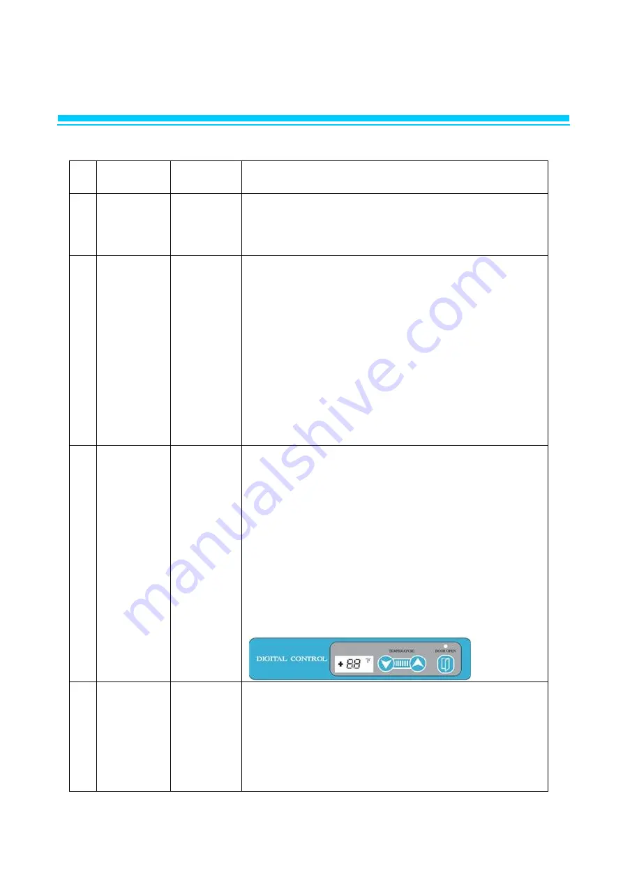
6. ELECTRONIC CONTROL INSTRUCTIONS
6-1-2. FUNCTION TABLE & MANUAL DEFROST
NO
Function
Controlled
Part
Description
1
Initial
Operation
1. LED displays inside temperature.
2. Begins to run immediately if higher than 50℉ and
begins to run after 5 minutes pause if lower
than 50℉.
2
Temperature
Control
Compressor
LED
1. The Temperature can be changed by pushing up/down
buttons.
2. LED displays inside temperature
3. Buzzer buzzes 1 time whenever a button is pressed
4. Compressor automatically turns on and off by C-sensor
(Except error mode)
5. Comp. On/off temperature at C-sensor (℉)
Setting5.03.01.0-1.0-2.0
Comp On86321
Comp Off20-3-4-5
Setting-3.0-5.0-7.0-9.0
Comp On0-2-4-6
Comp Off-6-7-9-10.5
3
Defrost
Function
Heater
Compressor
1) Defrost function is controlled time interval setting.
2) Factory setting is every 8 hours.
3) If it becomes defrost cycle time, Defrost heater is
operated when D-sensor senses below 23℉.
4) Defrost heater terminates when D-sensor temperature
comes to above 53℉, then compressor will start after
10 minutes.
5) During defrost period, LED displays dF.
6) If D-sensor does not cut off defrost heater, main pcb
has a back up for defrost time, the maximum is
40 minutes.
7) Defrost can be set by pushing the button for 3 seconds.
(3h, 6h, 9h, 10h(ah) )
4
Error
Display
LED
1) Press `up' button 3 times while pressing and holding
`down´ button.
Above procedure switches normal display to error
display mode. And then 88 LED indicates, `(D1)' or
`(F3)'
or `(C1)' respectively.
2) 10 seconds after the last button pressed, error display
mode will be switched to normal display mode.
Содержание LRB-771PC
Страница 1: ...1 Commercial Upright Refrigerator Freezer Service Manual...
Страница 4: ...4 1 ASSEMBLY LRB 771PC...
Страница 6: ...6 1 ASSEMBLY LFB 771PC...
Страница 8: ...8 1 ASSEMBLY LRB 771PCG...
Страница 10: ...10 1 ASSEMBLY LRB 1471PC...
Страница 12: ...12 1 ASSEMBLY LFB 1471PC...
Страница 14: ...14 1 ASSEMBLY LRB 1471PCG...
Страница 38: ...38 3 WIRING DIAGRAM 3 1 REFRIGERATOR LRB 771PC LRB 1471PC...
Страница 39: ...39 3 WIRING DIAGRAM 3 1 REFRIGERATOR LRB 771PCG LRB 1471PCG...
Страница 40: ...40 3 WIRING DIAGRAM 3 2 FREEZER LFB 771PC LFB 1471PC...
Страница 41: ...41 4 PART DETAILS 4 1 TOP PANEL Display PCB Main PCB...
Страница 42: ...42 4 PART DETAILS 4 2 COMPRESSOR COMPARTMENT Condensing Unit LRB 1471PC LFB 1471PC LRB 771PC LFB 771PC...
Страница 70: ...70 7 REPLACEMENT OF MAIN COMPONENTS D Remove the hinge CAUTION DISCONNECT FROM POWER SOURCE BEFORE SERVICING...


