


ICS-6 Instruction Manual
01000-53-000
Page 12 of 42
Issue 11 19 January 2021
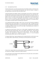
If the laser hazard is considered low, it is possible to use switches with only one safety contact. In
this case connect the switch across the ‘A’ terminals. Fit a wire link across the ‘B’ terminals. The
Mismatch Detector cannot be used and must be disabled, see the Mismatch Detector section below.
It is usual to use low voltage 4-core flexible cable for these connections and Lasermet can supply
suitable cable in standard PVC or low smoke zero halogen (LSZH) types.
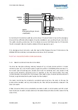
If an Interlock input is not used, one wire link should be fitted to connect the ‘A’ terminals together,
and a second wire link to connect the ‘B’ terminals on each unused terminal block.
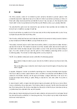
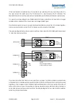
The example diagram below shows a system with two doors wired for ISO 13849 performance level
‘e’. Each door has two switches.
A
B
B
A
INTERLOCK
1
INTERLOCK
2
INTERLOCK
3
INTERLOCK
4
Door
Interlock
Switch 1A
Wire
Links
Wire
Links
NOTE:
Door Interlock Switches
shown with door closed.
Door
Interlock
Switch 1B
Door 1
Door
Interlock
Switch 2A
Door
Interlock
Switch 2B
Door 2
A
B
B
A
A
B
B
A
A
B
B
A
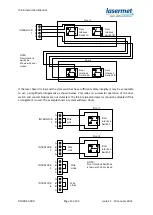
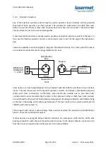
If you have more than four doors you can wire them in groups. A common situation is where there
are double doors. Interlock switches need to be fitted to both, and the two doors can then be wired
together so that a single monitor indication light will illuminate on the front panel of the ICS-6 if
either of the doors is open. The switches in a group should be wired with their safety contacts in
series. Each group may have several switches. An example diagram for two door interlock switches
wired in a group is shown below.


