


ICS-6-DLSM Instruction Manual
01692-53-000
Page 8 of 20
Issue 3 30 January 2020
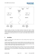
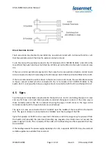
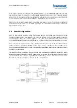
Switching Unit Mode Selector
The mode selector switch may be a single keyswitch with four contacts or an ISMECH 2/2 door
switch fitted. The switch needs to have two contacts which close in one-room mode only, and two
electrically separate contacts which close in two-room mode only.
From selector switch
8-core 7 strand
When the selector switch is in the one-room position the relays in the switching unit are powered
and they change the B area circuits over from the B ICS to the A ICS (one-room mode). When the
switch is set in the two-room position closed each ICS is responsible for its own area.
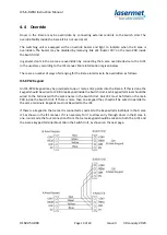
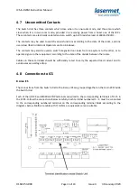
4.1 Switching Unit Power Source
The switching unit takes power from either or both ICS’s. A power-commoning arrangement in the
switching unit can be used to provide 24V and 12V power to signs, keypads and shutters provided at
least one ICS is turned on.
The ground / 0V connections of the ICS’s are joined together.
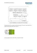
Connect the power supplies from the two ICS’s to the Switch Unit as shown below. Make sure to use
cable of sufficient cross section to carry the expected total load of equipment that may be powered
by the Switch Unit. It is suggested that a minimum of 16/0.2mm cores are used. This may need to be
increased if there is a lot of equipment such as maglocks or low voltage signs to be powered or if the
cable run is long.
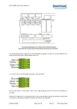
For the following circuits multicore cable using 7/0.2mm conductors is usually sufficient.


