ICS-6-DLSM Instruction Manual
01692-53-000
Page 11 of 20
Issue 3 30 January 2020
O-PCB Failsafe Timer
The B area doors may be overridden by a momentary contact such as a pushbutton or access control
system in conjunction with a Lasermet O-PCB failsafe timer, which gives an override for an
adjustable limited time duration.
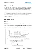
The O-PCB must be fitted in the sockets on the main PCB inside the Switch Unit and secured with an
M3 screw in the post provided.
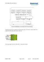
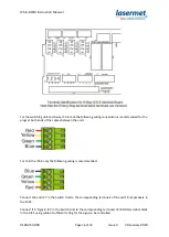
The external momentary contact used to trigger the timer is connected to the ‘B’ terminals of J24
‘O/RIDE IN AREA’ inside the Switch Unit. This contact must be normally open and close momentarily
to activate the override timer.
Link LK2 on the main PCB of the Switch Unit must be removed.
If there is a similar override arrangement in the A area the A area override activation
contact/pushbutton needs to be connected to the A ICS, and an O-PCB needs to be fitted inside the
A ICS according to the ICS manual.
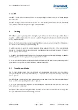
If the A override needs to override doors in the B area in one-room mode, the override
device/pushbutton needs to have a second contact which is connected to the ‘A’ terminals of J24
‘O/RIDE IN AREA’ in the Switch Unit. It is not possible to have a single contact connected to both the
ICS and the Switch Unit.


