PLMNL0243 REV. A, Effective Date: 03/24/16
36
FiberMINI ™ 2.0 Operation Manual
5.9 Adjusting the Optional Camera
Mount
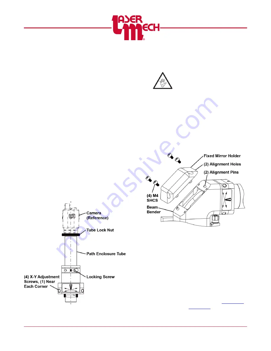
The vision system is usually adjusted after
laser focus position is found and the head
is located in the proper laser focus
position above the work piece.
See
Setting Vision Image Focus
1. Using a 1/8 inch hex wrench, loosen
the locking screw.
2. Adjust the path enclosure tube by
sliding it until the image becomes
clear.
3. Once the vision image focus position
is properly set, tighten the locking
screw.
Adjusting Position
The position of the vision system is
adjusted using the X-Y adjustment screws
on the camera mount.
4. Using a 1/8 inch hex wrench, loosen
or tighten the X-Y adjustment screws
until the image is centered on the
screen.
Figure 51
5.10 Servicing Vision Components
5.10.1 Fixed Mirror Holder
Before opening any part of the
head, clean off the dust and/or
process debris using an exterior
cleaning towel (PLTLS0023) or
equivalent.
To remove the fixed mirror holder:
1. Remove the (4) M4 SHCS
holding the fixed mirror holder in
place.
2. Take the fixed mirror holder to a
clean work area.
3. Protect and cover the opening in
the beam bender during service.
Figure 52
To replace the fixed mirror holder:
4. Remove the protective cover
over the opening in the beam
bender.
5. Verify that the (2) alignment
holes in the fixed mirror holder
and the (2) alignment pins in the
beam bender are in-line.
6. Replace the (4) M4 SHCS that
hold the fixed mirror holder in
place.
7. Center the beam in the tip


