Ver.0118-1
SPLED-CL1B-MOD1
Larson Electronics LLC
2
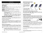
The solar panel surface must be kept clean to collect sunlight effectively.
CHARGING
With up to 5 hours of daily sunlight, this beacon is designed to function 15
hours. Ensure there are no obstructions that could result in little to no sun
reaching the panels.
MAINTENANCE
If the lens or solar panel becomes dirty, wipe down with a mild soap and
water solution.
Keep snow and debris clear of the solar panel so the batteries can charge. If
the panels are covered by snow or debris for an extended period of time,
allow the battery to charge in full direct sunlight for at least 5 hours for the
battery to reach its full capacity.
It is recommended to occasionally inspect the unit for any defects.
TROUBLESHOOTING
If for any reason the LED beacon does not power on:
Batteries not fully charged:
Make sure the fixture is placed in an
area where the solar panel gets the maximum amount of full, direct
sunlight every day. If the solar panel does not receive enough sunlight
during the day (e.g. due to cloudy or overcast weather conditions), it
will be recharged on the next sunny day and resume operation.
Other light sources:
(For units equipped with a day/night sensor.) If
your solar light is located too close to street lights, porch lights or
other lights, the solar panel may turn off the fixture. Relocate the solar
panel or eliminate those other light sources.
Not enough direct sunlight:
Ensure that the fixtures are not installed
in a shady area, for example, in the shadow of a tree or a house. If
necessary, move the fixtures to an area that gets full direct sunlight.
Switch is in the OFF position:
(For units equipped with a power
switch.) Cycle power button in a dark room. The light(s) should come
on when the switch is in the on position if the unit is fully charged.
Flash Patterns
The CL1B LED Beacon is programmed with 30 different flash patterns listed
below. Temporarily toggle pattern switch to change.
Synchronous Flash Patterns
FP1: Single Alert 75 PHASE 1 (sim)
FP12: Single Flash 150 PHASE 2 (sim)
FP2: Single Alert 75 PHASE 2 (sim)
FP13: Single Flash 75 PHASE 1 (sim)
FP3: Quad Flash 75 PHASE 1 (sim)
FP14: Single Flash 75 PHASE 2 (sim)
FP4: Quad Flash 75 PHASE 2 (sim)
FP15: Single Alert 75 (alt)
FP5: Double Flash 150 PHASE 1 (sim)
FP16: Quad Alert 75 (alt)
FP6: Double Flash 150 PHASE 2 (sim)
FP17: Double Flash 150 (alt)
FP7: Double Flash 75 PHASE 1 (sim)
FP18: Double Flash 75 (alt)
FP8: Double Flash 75 PHASE 2 (sim)
FP19: Single Flash 375 (alt)
FP9: Single Flash 375 PHASE 1 (sim)
FP20: Single Flash 150 (alt)
FP10: Single Flash 375 PHASE 2 (sim)
FP21: Single Flash 75 (alt)
FP11: Single Flash 150 PHASE 1 (sim)
(sim): Front and rear LEDS fire simultaneously
(alt) Front and rear
LEDS alternate
Non-synchronous Flash Patterns
FP22: Single Alert 75 PHASE 1 (sim)
FP27: Single Flash 150 PHASE 2 (sim)
FP23: Single Alert 75 PHASE 2 (sim)
FP28: Single Flash 75 PHASE 1 (sim)
FP24: Quad Flash 75 PHASE 1 (sim)
FP29: Single Flash 75 PHASE 2 (sim)
FP25: Quad Flash 75 PHASE 2 (sim)
FP30: Single Alert 75 (alt)
FP26: Double Flash 150 PHASE 1 (sim)
(sim): Front and rear LEDS fire simultaneously
(alt) Front and rear
LEDS alternate
Setting the Flash Pattern
Each pattern can be selected by pressing the momentary toggle switch. The
selected pattern will remain during power cycles.
•
Less than 1 second for the
NEXT
pattern
•
1 to 3 seconds for the
PREVIOUS
pattern
•
3 to 5 seconds for the
DEFAULT
pattern
•
Greater than 5 seconds to
TURN OFF
the beacon
9419 US-HWY 175
Kemp, TX 75143 USA
P:
800-369-6671 | INTL: 903-498-3363 F:
903-498-3364
www.larsonelectronics.com


