LT-3100S GMDSS User & Installation Manual Rev. 1.02
Interfaces
Lars Thrane A/S
www.thrane.eu
Page 23 of 71
Interfaces
LT-3110S Control Unit
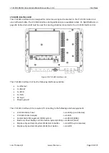
This section will describe all the external interfaces to the LT-3110S Control Unit, including the coaxial cable
interface to the LT-3130 Antenna Unit.
DC input
The LT-3100S GMDSS system is designed to be used on 12 VDC and 24 VDC power buses (nominal). External
DC power to the LT-3100S GMDSS system is provided by connecting the proprietary 91-102118 power
cable, 3m - delivered by Lars Thrane A/S. The power connector is mounted on the back side of the LT-3110S
Control Unit
and marked ‘PWR’
, see Figure 3 on page 7.
NOTE
:
The input voltage range is: 12 - 24 VDC. The LT-3110S Control Unit DC input connector and
circuit is protected and certified for
Reverse Polarity Protection
. Use only the 91-102118
power cable, 3m delivered by Lars Thrane A/S.
Chassis ground
The chassis ground connector is placed on the back side of the LT-3110S Control Unit and marked with
‘GNDC’
, see Figure 3 on page 7.
SIM card
The LT-3100S GMDSS system requires a GMDSS SIM card to be operated with the Iridium® satellite
services. The Iridium® GMDSS SIM card must be bought from one of the official Iridium® GMDSS Service
Providers. A list of Iridium® GMDSS Service Providers can be found at the Iridium® website:
https://www.iridium.com (
select ‘
Services
’, and hereafter ‘
GMDSS
’
).
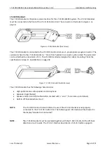
The GMDSS SIM card must be inserted in the LT-3110S Control Unit behind the rubber dust cover. Make
sure that the LT-3110S Control Unit is powered off before opening the rubber dust cover. When the GMDSS
SIM card is properly inserted in the slot, and the rubber dust cover is secured, the LT-3110S Control Unit
can be powered up. The rubber dust cover is illustrated in Figure 3 on page 7
and marked with ‘SIM’.
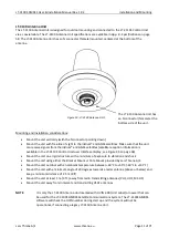
The following procedure must be followed when inserting, replacing, or removing the GMDSS SIM card:
1.
Turn off the power to the LT-3110S Control Unit
2.
Remove the rubber dust cover on the back side of the LT-3110S Control Unit
3.
Slide the SIM card holder as illustrated with the arrows on the PCB print, to unlock
4.
Open the SIM card holder and insert or remove the SIM card
5.
Close the SIM card holder
6.
Slide the SIM card holder as illustrated with the arrows on the PCB (opposite direction), to lock
7.
Re-insert the rubber dust cover
8.
Turn on power to the LT-3110S Control Unit
Содержание iridium LT-3100S
Страница 2: ......
Страница 83: ...Lars Thrane A S Skovlytoften 33 2840 Holte Denmark www thrane eu...

